Jumping to that line is normal, it’s the first one that takes a few seconds that’s why it hangs there.
Can you try a longer tool? That really is the only explanation I can think of right now…
Jumping to that line is normal, it’s the first one that takes a few seconds that’s why it hangs there.
Can you try a longer tool? That really is the only explanation I can think of right now…
Because this is MicroJig’s roughing bit for their dovetail, I can use a longer .25 compression bit if length is the problem. Not sure if my 1/2 x 14 degree Whiteside dovetail bit is much longer but I’ll check it out tomorrow morning when I get back in the shop.
I’ll let you know what I discover.
A longer tool did not work.
I went as far as setting my WCS to the front right corner in Vectric. This keeps me from fudging the numbers in the WCS, since my SB is too close to the tool setter to use the touch plate.
I have plenty of XYZ limits, so I don’t understand this one bit. All I want to do is start creating projects and use my new machine but this is frustrating. I don’t see what the issue is. I’m not mad, just discouraged I can’t move beyond this point. It’s been days. ![]()
I was going to buy a collect extension but not going to waste money for nothing because tool length is not the issue.
Maybe we need to schedule a 1/2 hour session and work on this together. Today is not good for me but I could do next Monday. I’m EST so morning is best for me after you guys get in. Should I email support to schedule this?
Would it help if I generated a report and send you the zip file for review?
I have to leave here at 2:15pm my time today so I’m available til then.
Eric,
I will give this a try when I get back home. I did set up a scheduled appointment with you for next Monday morning.
Thanks,
Jay
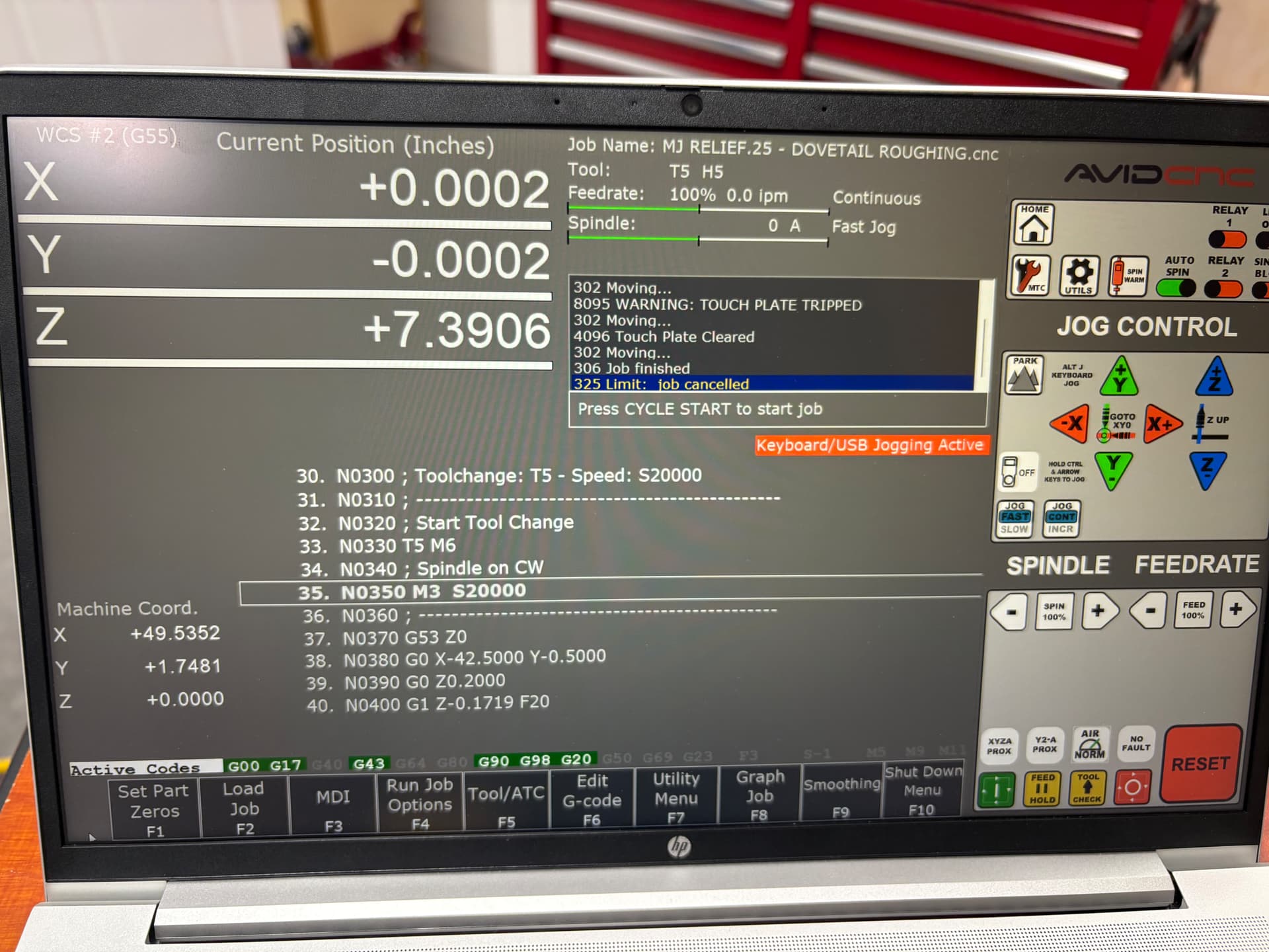
I did as you suggested and found a Z -7.4507, so I overwrote it to be 0.0000
Everything was all set up prior to do this.
I went to start the job and I thought it was going to work but it gave me the same Z error. No G23/G22 ever displayed.
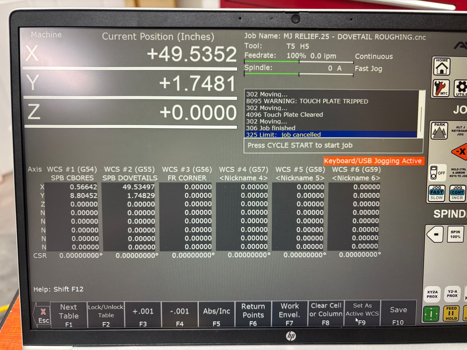
I went back to the Set Part Zeros>WCS CRS Table>Work Envel.
And a different -Z value was displayed. See photo.
I’m done for the day. Any other ideas, leave them here and I’ll attempt to do them tomorrow.
The only other thing I can think of is that you somehow changed your Z travel settings…
You’re absolutely positive that you can go to MDI and then type in Z -.3438 and the machine will go below the spoilboard (after you press cycle start)
Because that command is all that G code is doing, if you can do it in MDI then I cannot fathom a reason it wouldn’t work with the G code you provided above.
I noticed in the gcode provided, that there’s a G40 (cutter compensation off) and an M6 (tool change) but no G43 (tool length offset) or G49 (cancel tool length compensation), despite at least on of the screenshots showing G43 active. Could the machine be getting confused about the tool length? Is there a way to ask the system what it thinks the current tool offsets are?
Those are all in our M6 script
@Jaybird64 Have you tried re-running the MTC button to touch off that tool again and trying this?
Positive. I’m using a .25 end mill to rough out a channel at that depth for this tool path and then afterwards, I’ll use a tool path to finish the channel with dovetail bit at .375 deep. I have used the MDI to do Z-.375 and it will go to that depth, no problem.
I know! That’s what’s so confusing about this. It makes no sense. Is it possible that there’s a different problem with my XY and it’s falsely reporting a Z error? I’m just grasping at straws here because I don’t know this controller software. But I’ve been around enough engineering software where I’ve seen phantom issues that were masked by false positives, if that makes sense?
Absolutely! After homing is complete, I do UTILS> 2 for tool setter and Y to set spoilboard height.
I have also done MTC redundantly to make sure the tool is measured properly.
I just remembered when I first called tech support about this issue, I told them I originally mounted my tramming plate a little higher than what the instructions called for. The instructions says to mount the plate at 3-3/4" from the bottom edge and I had it about 1.25" higher, thinking I would be using longer tools. Before I even started the tramming setup for tilt and nod, I physically moved the tramming plate down to the suggested 3-3/4" dimension.
I don’t see how that would be affecting any software issues at this point, but I thought I would mention it.
You only have to do this once, not every time you home
You have to do this every time you install a new tool
If in MDI you can go to the z NEGATIVE height that’s in your G code everything should work… if it doesn’t there something very very odd and obscure going on here…
Yes, Homing once, followed by Tool Setter 1 time and MTC each time for swapping out tools.
Ok everyone, got it solved: Turns out the “spoilboard dig-in” setting despite being off wasn’t actually off. I manually turned it of and we’re good to go!
The bad news. Another glitch in the matrix!
I ran the finish groove with a 1/2 dovetail bit and it put all the grooves in properly except for the closest groove near the home position for WCS #2. Despite the G-Code being correct it’s shifting that last groove over 2” to the left of where it should be. All grooves are 5” on center.
It’s basically the same code as before except for a tool change.
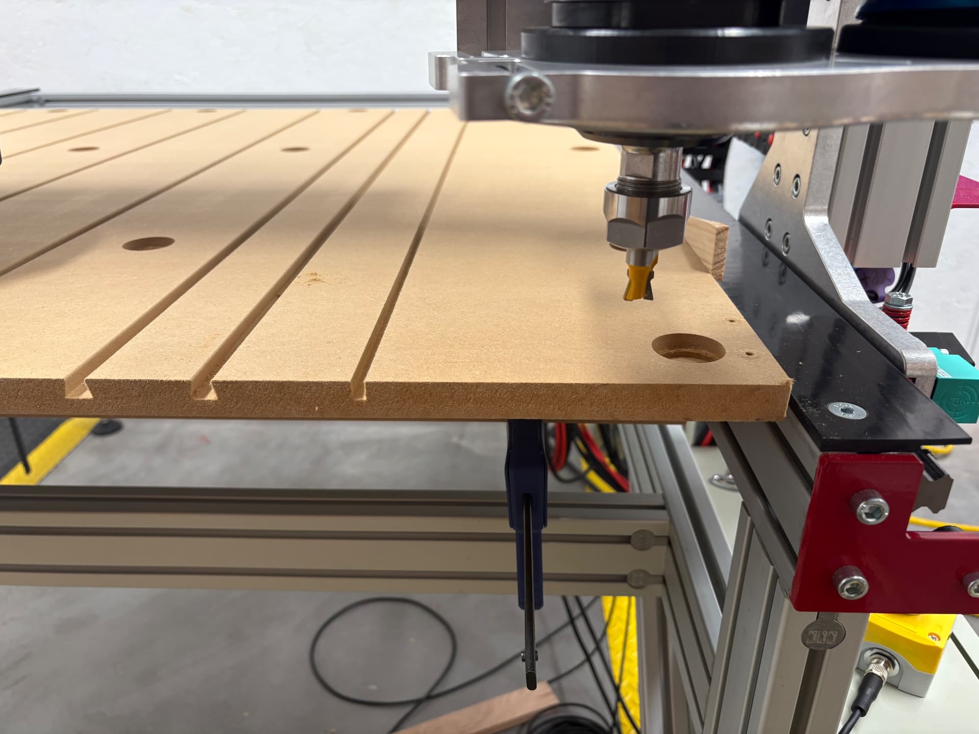
The picture I’m attaching shows the router bit where it thinks home is for WCS. As you can see, it is probably 2 1/2 inches from the corner.
Also, you can see three grooves. The center groove should. not be there and it was not there on the first pass with a quarter inch end mill.
You can see the groove where the .25 mill correctly placed the channel. However, the 1/2” dovetail decided to put the groove a little over 2 inches to the left of where it should be.
Can you post both G code you ran (the slot and the dovetail) so I can compare them?
Sorry, I got the problem fixed. Not sure what caused the issue. But I regenerated the code for just that single groove that it missed and it worked after I performed another outside corner plate to obtain a new XY location to G56 (new). It was close enough to the same coordinates for G55 that I just went with it. Anyway for whatever ever reason, doing another Set Part Zeros did the trick.
I forgot to mention that the error it was giving me was an X-limit. That’s why I redid the Set Part Zero.
I wonder if we (I) might have messed that up when we were in the set part zeros menu messing around…
I don’t think so. I surmised while I had to step away from the machine to talk with you while it ran that first pass, I noticed the plastic shoe was slightly rotated, but not til it messed up on the last pass. I don’t like waking away but I had no choice. Maybe if I used tool check to stop the job briefly?
I think the shoe barely skimmed the top of one of the clamps, if the clamp vibrated loose. They were still in place however. The shoe was snugged tight. This is my only best guess after inspecting everything. So maybe it got held in place for a second and then just decided to groove where it got hung up at in the X-axis?
Luckily, no damage done.