First of all I am not sure what is causing this, the post processor, fusion, or a few brain cells shorted out. I am trying to cut some table legs for an angled table, yes I could do this on my table saw, but figure this would be learning exercise for the rotary. There are two issues I am experiencing with cutting this, both come down to the X axis coordinates created in the post seem to be wrong. I was able to machine both front legs and they look fine, however when I went to machine the Right Rear Leg, ( 4th manufacture stepup ), on the first Corner Cut (5th operation), what happens is the bit does not cut all the way through. Instead it ends short of the full width of the corner. If I extend the pass by .7-1 inch or so I am fine, but on the simulation it works perfectly, just in real cutting it does not. And looking at the generated gcode and moving the spindle to where it says, it is doing exactly what was processed. (this issue was present in both front legs as well, but I just put the in the compensation and proceeded.
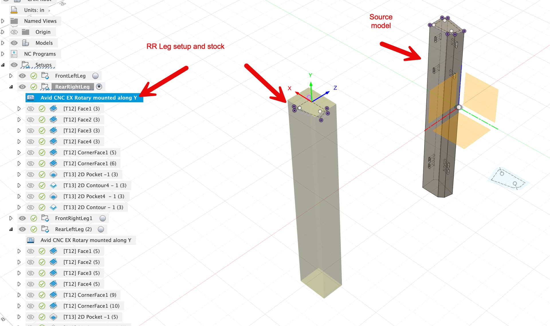
Second issue is when I get to the 2D Pockets, these are pockets for dominos, these pockets on the first side in the Rear Right Leg setup was totally off. Instead of putting the pockets where the should it seems to have moved to the wrong side, where the X coordinates are off. And really looking at it, things are even what I would expect backward. My rotary is mounted along the Y axis with the motor at the max Y limit and max X. My setup is shown in the image below, along with what it actually cut, like it rotated it. And since I am not in the shop now, I am going to have to go look at the two front legs closer to make sure things are where they should be.
I have attached the entire fusion 360 file of the entire design, the resultant gcode for this setup. Please don’t be too harsh on the design ![]() But if any one can see why this is not cutting right, please feel free to smack some monkey knowledge into me. Any help is greatly appreciated, especially before I give up and use the table saw and then end up cutting it 23 times to get it right there as well…
But if any one can see why this is not cutting right, please feel free to smack some monkey knowledge into me. Any help is greatly appreciated, especially before I give up and use the table saw and then end up cutting it 23 times to get it right there as well…

angled_end_table_v2 v39.f3d (1.0 MB)
RLL-try3.txt (41.2 KB)
Thanks,
Tim