Another data point, I looked at the acceleration rates of all the axis. Y and X have rates that translate into .13G’s. Z is half at .07g’s. I previously lowered the A axis rates down from 2.5 to .5 g’s. I’ve now tested increasing the Z acceleration by double to .13 and slowing the max rate and acceleration of the A to 19RPM and .07g’s respectively. This has reduced the slipping, but slowed the whole process down a lot. I can deal with that, but it’s also making the non-smooth nature of the program really evident by slowing things down. Also, as I now understand the G94/G93 nature, all of this is G93 nearly from the start(no surprise).
My money is on lost steps due to high torque of the angular acceleration of a large cylinder. How heavy is the cylinder?
If you put your hand on that cylinder (try to restrict rotation) to give it even more rotational resistance do things get worse?
Have you tried hand-editing those few lines where you have Z-reversals? Change the feeds there to something smaller during the 2.5 degree increments? I don’t know if something like that would work, but if you have a problem in just one part of the program, it would be ideal to fix just that part of the program rather than slow everything else in the program down just to accommodate that one area.
It’s most certainly pushing the limits of the equipment due to the weight of the part, which is why I’m able to accomplish a successful pass with it way slowed down. I’m just hoping to create a program that is generally smoother.
While I could go find all of the areas where there is a reversal, and possible find some modification that would make it smoother, the shear size of this program with .25" stepover for roughing would make that more than arduous. Even when there isn’t Z axis reversals, there is still much jerkyness to the A axis. It’s running point to point. I am hoping to find something that “blends” if that makes sense.
I understand. It doesn’t help you now, but CNC12 has sets of smoothing settings that help with that sort of thing. What CAM are you using? Fusion smoothing might be able to make the transitions a little less severe at the G-Code level.
FWIW, I have also seen the ‘jerkiness’ with rotary G-Code from Fusion. I’ve got CNC12 and servos so there isn’t much of a downside rather than its sort of hard to watch. Hence my interest in your problem.
I have also noticed that parallel finishing passes on these bowls are slightly more accurate when cutting along X vs around A. Not sure why this is, might be the same thing you are seeing.
I also use cnc12 and fusion and run them in “precision router” as this pattern ends up with stair-stepping in the valleys with the less precise smoothing modes.

So with the CNC12 and Servos, is it not a problem because it has more power? If it were to slip, would it just halt the program because it detects it’s out of alignment?
Sorry for my ignorance, what is “precision router”?
I’m assuming it is part of the controller software for CNC12?
And Grossmsj, I’m running Fusion 360 with the manufacturing extension.
CNC12 gives various smoothing routines that you can use. If you don’t need precision, you can use contouring router, for example. “Precision router” is another choice for finely detailed work. There are probably other things in CNC12 that I just don’t know about or understand, but many people who switch from Mach4 to CNC12 comment on how much smoother it is.
I have a CPM-SDSK-3436P-ELN Clearpath servo (900 oz-in) on my rotary. You are right, if you over torque it the program stops, which ain’t good. The servos also have their own ‘anti-jerkiness’ function which might add to overall smoothness. But servos aren’t panaceas for sure.
Have you tried any modifications with tolerance and smoothing in Fusion?
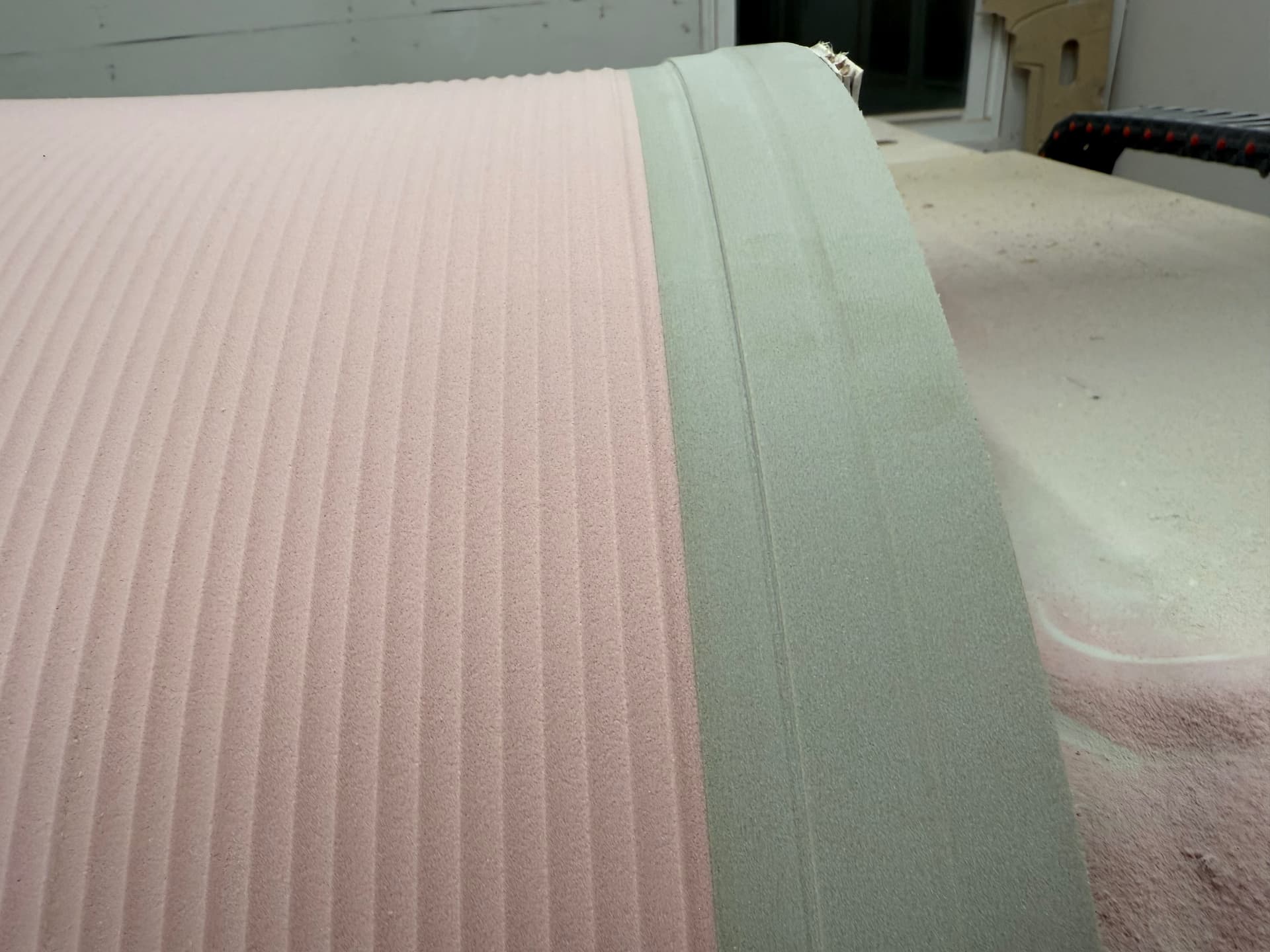
I did try a smoothing with a .001" tolerance, simultaneously I switched to a spiral from a parallel and the G code count went way up. I’ll play with that a bit more, but after some more thought and conversations with Avid, the simple math is that if the Z has to reverse directs, that means it has to stop first. If it stops, so then must the A axis. I have successfully run a rest program that roughs and also finish strategy on the dimensionally critical ends. I left everything .200" fat. I’m very happy with the results, even though it took forever and a day to complete. I’ve only got to do one of these, so if it takes a while, so be it. Clearly the size of my part is pushing the mechanical capabilities of the rotary components. I’m thrilled that ultimately it is working! I’ll post a couple progress pictures. I think I may 3d scan the ends just to verify the dimensional accuracy prior to making the final cut. I’m attempting to achieve .010" across a 30" diameter part, so I’ll use every tool I have access to! Thanks for all of your input everyone, and feel free to add more:)

Glad you got a successful result! You were definitely pushing limits there. Physics can be hard to overcome.
It seems Fusion can be made to be a little more graceful with rotary operation. I understand what you were observing, and I’d like to find a way to get around this in the future. But I use the manufacturing extensions by credits, and the $33 cost is a bit rich to just go out and play with it.
Scott
I discovered another attribute that has helped. I’m embarrassed I didn’t think of it before. I had the tolerance set at the default which is .0004". That explains the half a million lines of code to run this pass. I changed it to .001" which is what I normally set. Also, the smoothing function only complicates the program as far as I can tell. I set the smoothing as high as 1.000" distance between moves, and it did not significantly change anything from when it was set at .001". It takes forever to compute the tool path either way. I eliminated that and have not found any degradation in smoothness of the rotary axis. It seems to be slightly smoother with the tolerance set to .001" as opposed to .0004". I may even be able to speed up the feed so I don’t need to babysit this for 6 straight hours:)
Smoothing is constrained by the set tolerance. The curve derived from smoothing must fall within the set tolerance of the designed points. So if the tolerance is very small, smoothing won’t do much and it will take a lot of calculating. If the tolerance is significantly larger, you may see benefits from smoothing. You’re the only one who can decide how tight the tolerances need to be. I mostly work with wood, so a tolerance of 0.001 is pretty small relative to the wood’s ability to move.
There is also a feature in Fusion that will let you see how many fewer points you get with smoothing and where the smoothing is having the largest effect.