Hello all! I just got my new EX based machine and have been watching many of the Avid provided videos on the assembly and setup. One specifically that I liked was the job setup/zeroing the x, y and z on the new EX controllers and CNC12. In the video, Eric with Avid uses a laser crosshair to locate the work surface x and y zero. I have found the link to the laser that Eric used, but no idea on how it was mounted other than that Eric used a custom printed mount for the laser. The link is here:
I was wondering if anyone has the files to print your own mount or if anyone has any ideas on how to mount a laser crosshair or anything related to that. It would be helpful.
It doesn’t matter how you mount it. Just make sure it won’t move around.
You could have it 10mm or 10 feet away from your spindle. You just have to calibrate the offset. It’s all done in the Set Part Zeros menu, very simple.
That laser is a good one, but you also can use just about anything. On another machine I have an old cat toy laser screwed to it. Works great.
If you 3D printed the mount for your Avid CNC, can you share the STL files with the community so we can use the same type of mount? I like the unit I sent the link for, which I am told is the one that you used.
You might want to use a STEP file if you’re printing on a Bambu printer. You’ll likely get better quality. You can create an STL from this file as well.
This is really cool, I’m curious about how the offset is managed since it’s similar to what I’m doing in my Paper Tools software. It sounds like you zero the WCS, and when you load a GCode file the origin is based there?
What I’ve done is tape one of my “square targets” at a known position.
In my Camera Setup, the Paper Tools software determines the offset by moving the machine so the camera is positioned directly over the target. That determines the offset.
But as I’m moving around and I can see the target, I also determine an “affine transformation matrix” which lets me map any pixel in the camera to a machine position. From then on you can jog around by clicking in the camera view, and you can tell the machine to swap between the camera and the tool positions.
I have set the offsets in “Set Part Zero / Laser” menu. X offset seems to work. However the Y offset is set to 2.0402 but when I goto zero the Y axis only moves about .2 inches. Any idea what may be wrong?
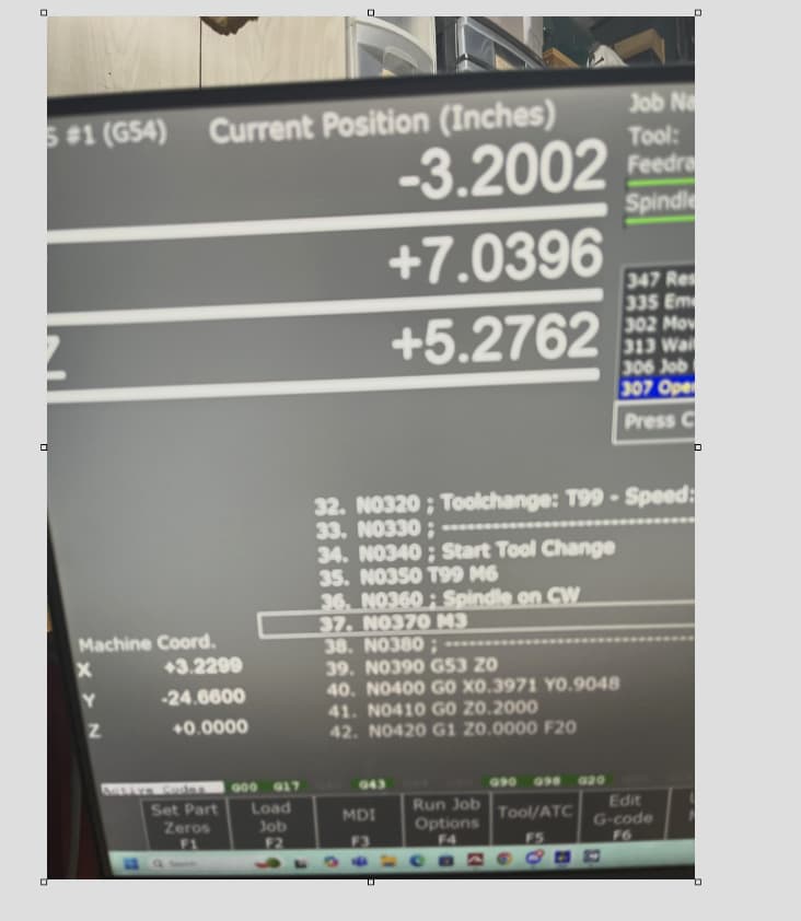
Another funny thing that does not seem to be correct to me. That is when I home all of the axis goto to 0 in machine coordinates. When I move my machine to the place that I cut at the Y machine coordinates go negative.
I have been able to cut and use the laser to cut a number of parts correctly.
100% sure that the machine coordinates in the Y direction go negitive. How can I correct it?? See below for a picture of moved with negitive Y, a picture of homed and a picture of my config. Do you need other information?
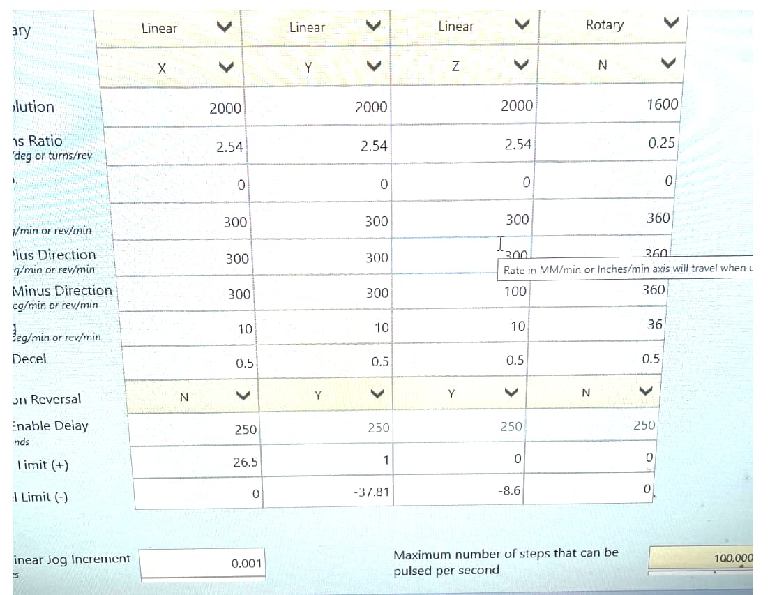
Sure looks like that’s how you have it setup, but if that’s a stock Avid machine none of our machines are setup that way. You also have axis reversal wrong, which makes me think that you might have tried to correct for that by having a negative Y travel?
I have a Stock Bench Top Pro configured exactly like the pictures on the WEB site. Whjat could be wrong with my configuration that has the Y machine coordinates be negitive?
The y limit (-) should be zero, and the (+) limit the the positive (38.81) to have home be by your tool height setter and machine coordinates always be positive.
Just to be sure you are talking about a small crosshair laser that you installed? If so did you teach offsets with the f8? And then set your parts position 00 x and y once you line it up with your crosshair laser.
If I use the go to XY 0 button then move the gantry towards me I will get a y negative