First of all I am not sure what is causing this, the post processor, fusion, or a few brain cells shorted out. I am trying to cut some table legs for an angled table, yes I could do this on my table saw, but figure this would be learning exercise for the rotary. There are two issues I am experiencing with cutting this, both come down to the X axis coordinates created in the post seem to be wrong. I was able to machine both front legs and they look fine, however when I went to machine the Right Rear Leg, ( 4th manufacture stepup ), on the first Corner Cut (5th operation), what happens is the bit does not cut all the way through. Instead it ends short of the full width of the corner. If I extend the pass by .7-1 inch or so I am fine, but on the simulation it works perfectly, just in real cutting it does not. And looking at the generated gcode and moving the spindle to where it says, it is doing exactly what was processed. (this issue was present in both front legs as well, but I just put the in the compensation and proceeded.
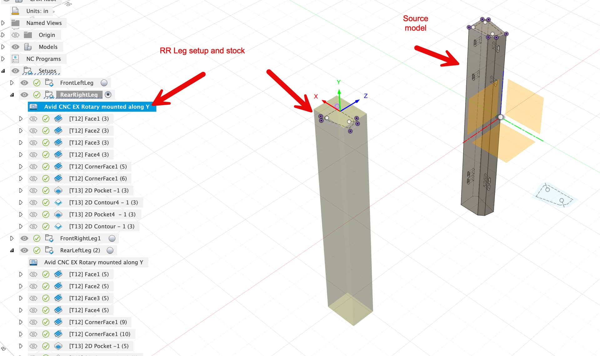
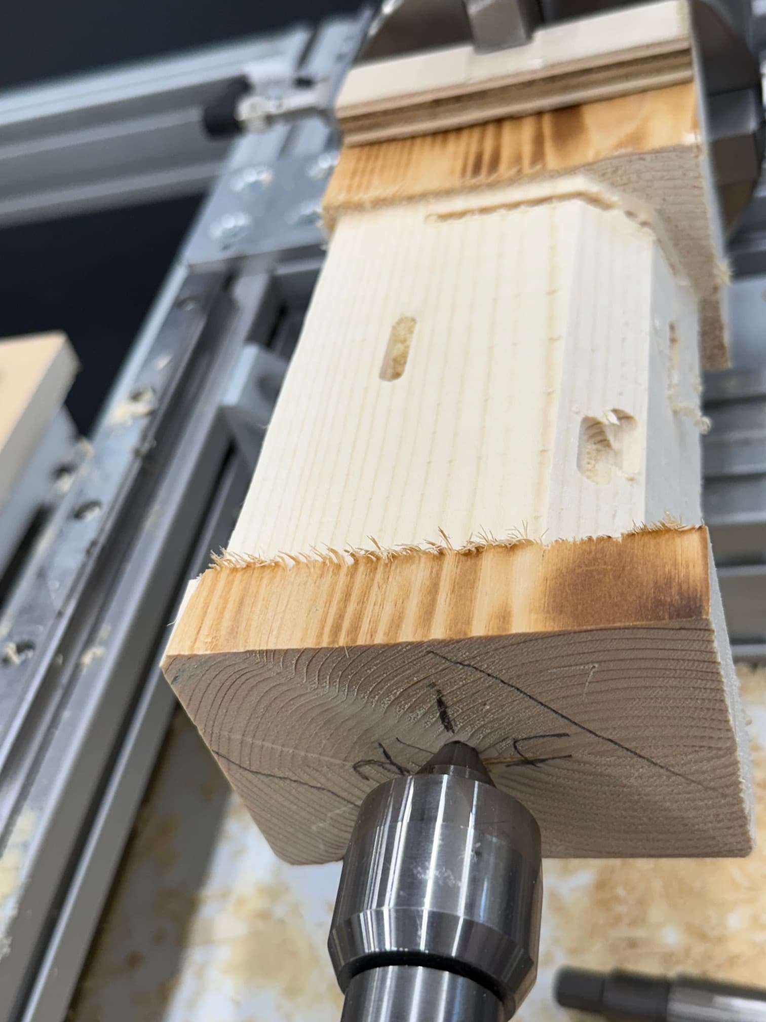
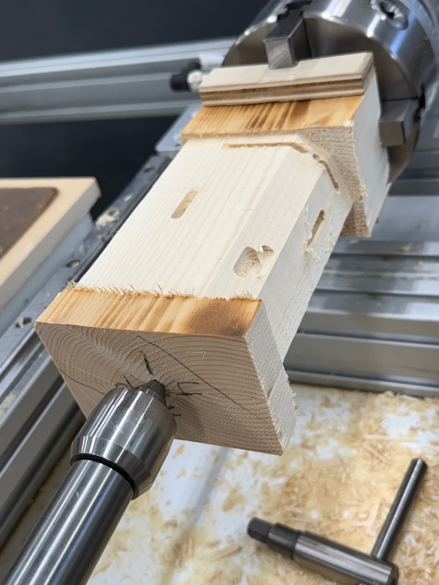
Second issue is when I get to the 2D Pockets, these are pockets for dominos, these pockets on the first side in the Rear Right Leg setup was totally off. Instead of putting the pockets where the should it seems to have moved to the wrong side, where the X coordinates are off. And really looking at it, things are even what I would expect backward. My rotary is mounted along the Y axis with the motor at the max Y limit and max X. My setup is shown in the image below, along with what it actually cut, like it rotated it. And since I am not in the shop now, I am going to have to go look at the two front legs closer to make sure things are where they should be.
I have attached the entire fusion 360 file of the entire design, the resultant gcode for this setup. Please don’t be too harsh on the design But if any one can see why this is not cutting right, please feel free to smack some monkey knowledge into me. Any help is greatly appreciated, especially before I give up and use the table saw and then end up cutting it 23 times to get it right there as well…
Another issue that’s gotten me a few times is using “relative stock”. I like to be explicit about what my stock is if it’s a cube or a cylinder. If it’s anything else I draw a solid for it and use that as the stock.
To really suss this out I’d make a VERY simple model of something like a simple L shape or an arrow.. something you could test out to see if it’s cutting mirrored.
Rotary stuff can be hard, but once you get it figured out there’s a LOT you can do in Fusion. This type of model is perfect for Fusion as it really takes advantage of the true 4th axis capability.
Well I did say Right rear but really meant I was cutting the rear left. Hadn’t really inspected the right rear for errors yet since I haven’t got there. I was about to do as you suggested and take that leg, and clone it to a separate project and cut it down to a few inches to be able to cut multiple test. But I am out of ideas on what to change on the rear left one, I’ll try the change to the stock.
So I have spent the last week or two trying to figure this out. I am pretty convinced it is a bug in either the post processor or fusion CAM. As I can not find anything that makes it mill right. However I could still be wrong.
My observations.
Entire part is rotate along the y axis. In fusion the +Y axis is facing away from us, on my machine that rotary is mounted along the Y axis with the chuck at the far +Y axis. If there was a chuck in the drawing it would be at the back where the sketch is lightly shown. Why is it not cutting as it is defined in CAM with the Y0 X0 is at the back of the part?
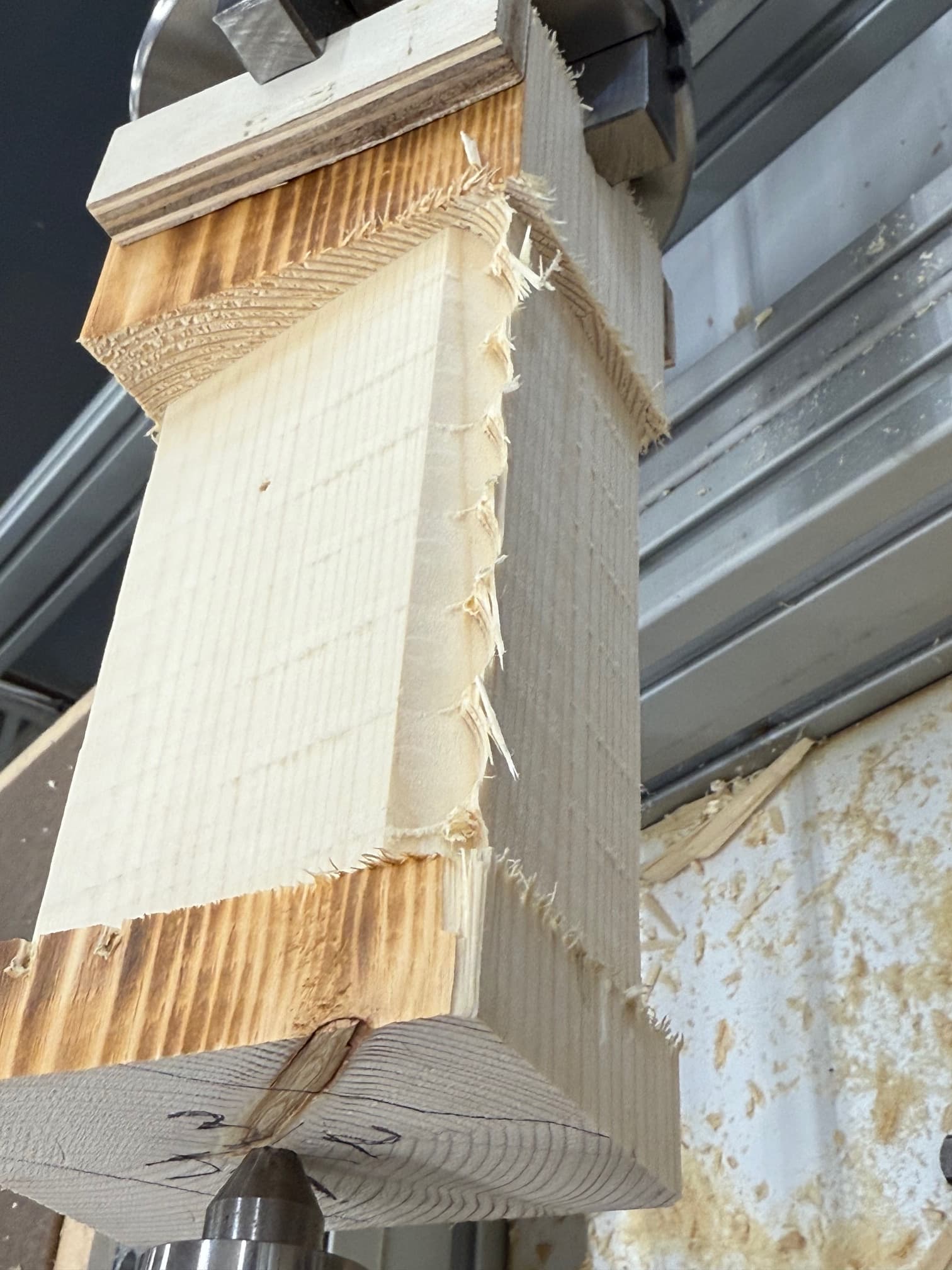
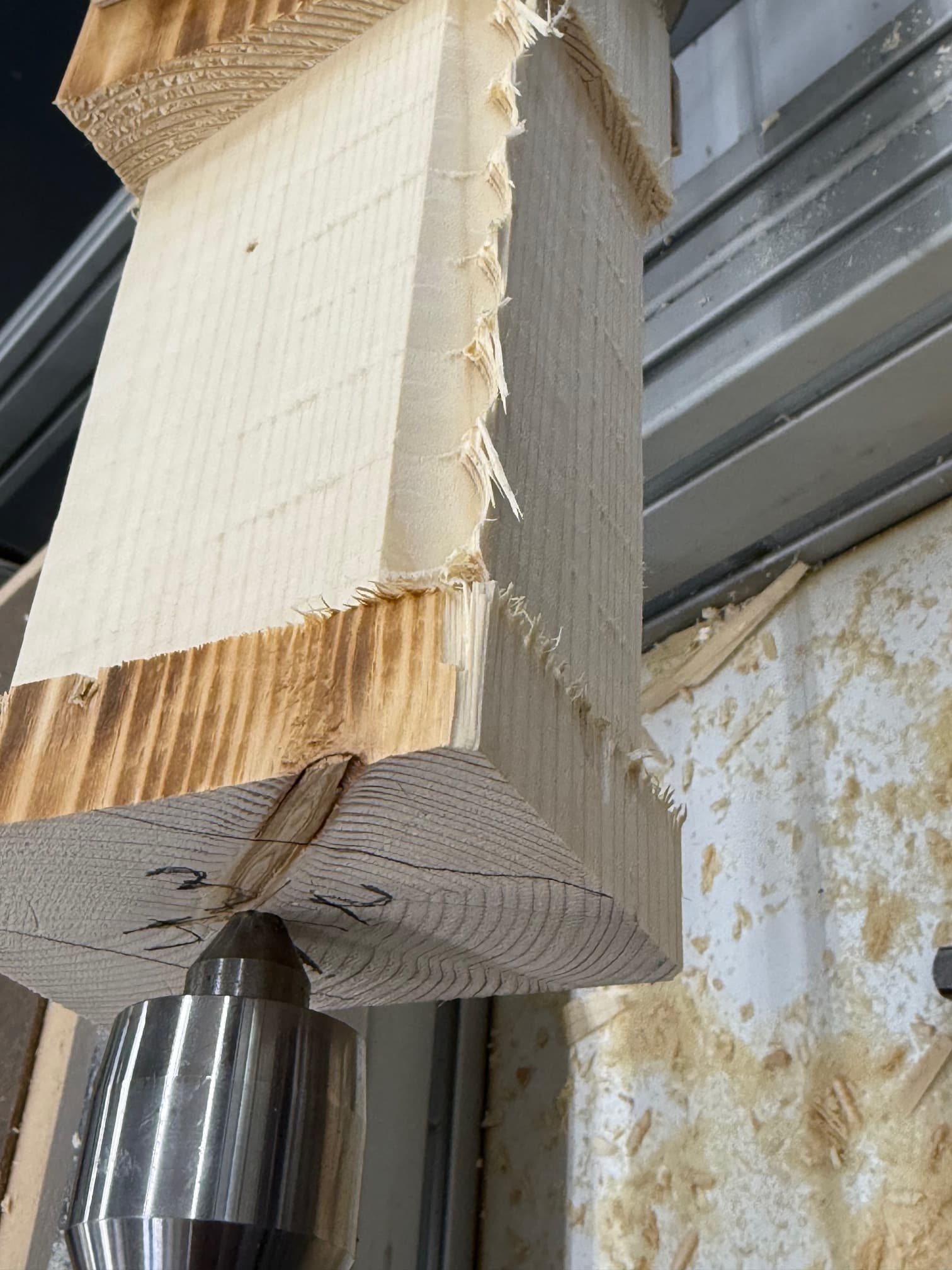
There is some issue, which I believe is related to the first, where when the part is rotated to cut the corner there is an issue where it does not fully cut on corner, in the simulation of Fusion 360 this cuts perfectly fine, and shows the bit where i expect it, in actual cutting it is offset, and never full cuts the corner between faces 2 and 3.
When it rotates to cut the slots, it does not seem to be putting them in the same offsets as the first 6 operations, and we no end up with the slots being cut into the corner ( since it is on the wrong side. The slots appear that the would be in the correct position if part want not rotate around the y-axis for the first operations.
I have numbered the faces and put a mark of which faces it should cut the angle tops and and even before cutting the piece show here I knew it would be wrong, because face 1 is the face on the fusion drawing facing up to the right and face 4 is the one to the left both with the slots in it. However when I rotated it prior to cutting based on the G0 A0 commands and labeled the end of the piece with the face numbers you can see that the intersection of face 1 and 4 are on the top right, not top left.
I have added the simple fusion test file to this post.
I have created a simple fusion test file and rand this multiple times, and am totally lost on how to get it to cut right. I am glad I started with common pine to test this on the project and it is all scrap 2x6
@Eric I wish you could try to cut this and see what you think. I am completely out of ideas. But something is definitely not working right.
You can see if I am looking at the end from the tail stock position, the top is face1, the right should be face 2, but it is face 4 from what it is really cutting in the pictures in the previous post. The Y axis is pointing in the positive direction toward the chuck, I wouid expect the actual cut to mirror this. Is it rotating the opposite direction from what fusion 360 is expecting? Is there somewhere where you can change the direction of rotation?
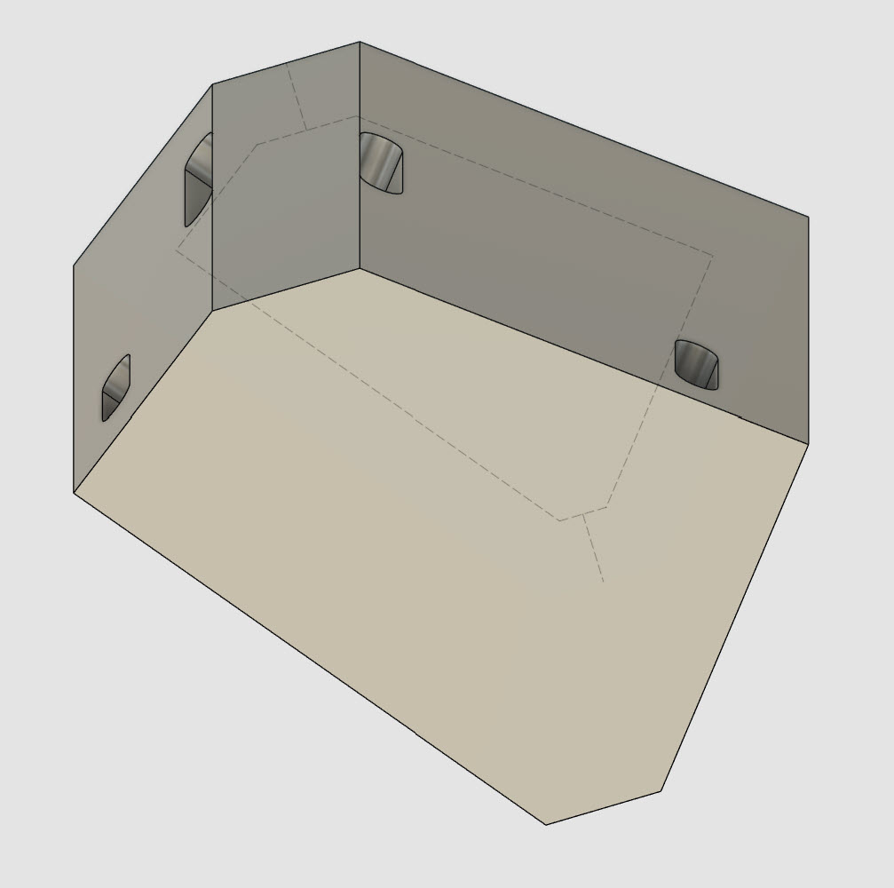
Also you notice this is what fusion thinks the cut path should be for the first corner cut, however it is not positioned correctly I beleive because it thinks the cut should be to the left of where it is, exactly like fusion is showing, but the code that is generated is off to the right side. This pic of the actual cut was rotated after it was done so it is not in the right orientation, should be more rotated to the left so it would be parallel to the cutting bit (between faces 2&3)
As far as I can tell your setup looks good. That being said my recommendation would be to try something even simpler: Just machine up a square, like this:
If you want to see a goofy demo I did with all kinds of crazy toolpaths you can check this out:
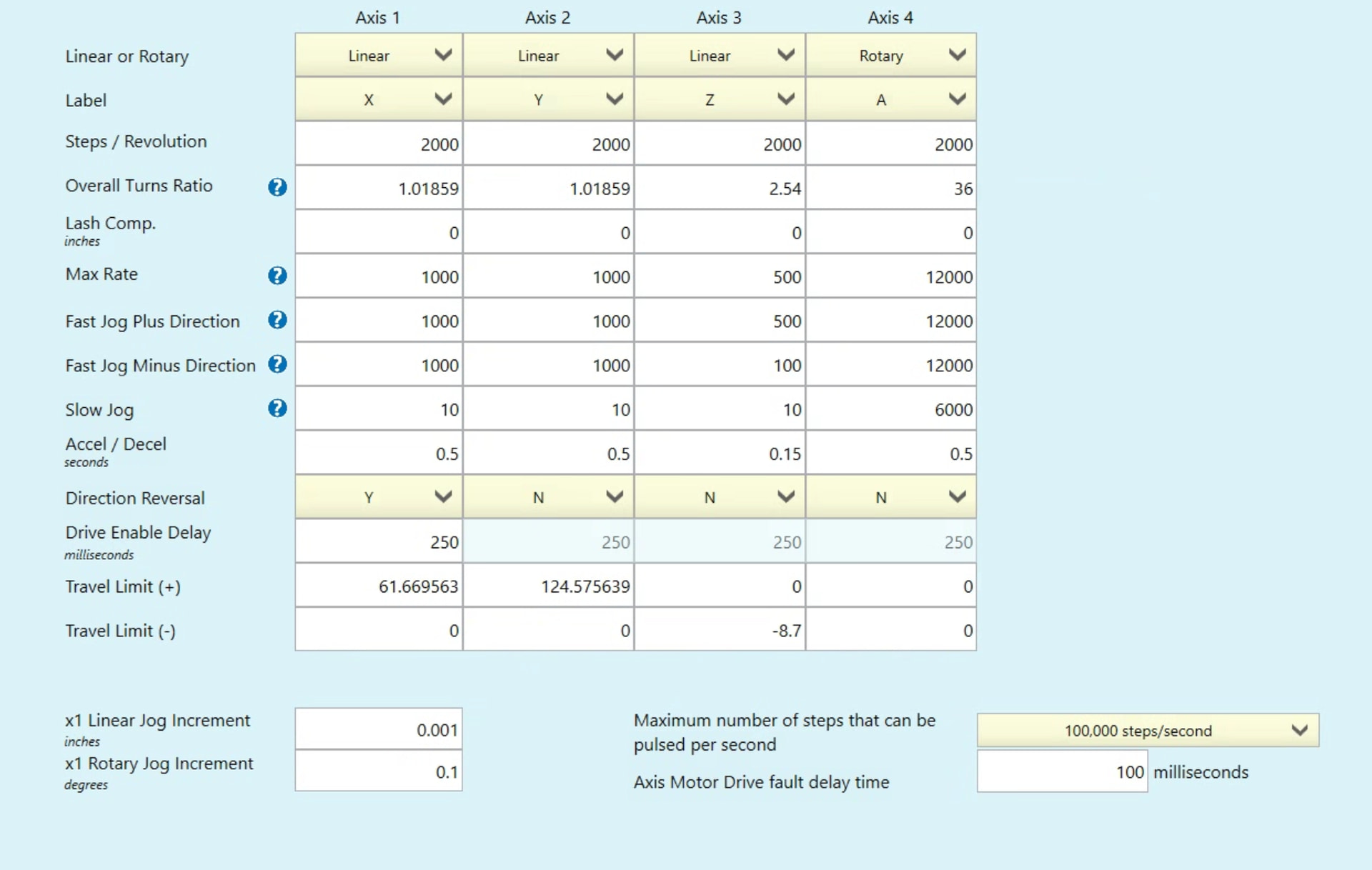
I took a quick spin through your file and I don’t see anything wrong with it. That’s pointing me to something wrong with your rotary calibration.
Have you checked it?
Chuck up a V bit, zero it to the tool height setter (normal MTC) then do “rotary recall” like you normally would do before running a rotary job. Clamp the little pointed cup we send into your jaws. Jog to Z zero, and then carefully jog so that the tip is touching the little pointy thing in your three jaw chuck.
The DRO should be at Z zero, and your X should be to. Your Y could be different because your rotary is orientated along Y, so you can set that 0 anywhere along the Y axis.
If that looks good move the V bit over to the tailstock and check it to see if XZ zero gets you right on the tip of it.
If those aren’t perfect you have a calibration issue.
SOLVED! The Autodex Fusion forum nailed it! Thanks to Scott for pointing this out. “you need to flip the rotary axis in the machine definition” As I said, my chuck is at the Max Y of the machine, the default Machine on the cloud expects it to be toward the Y0. So that is why the axis appeared to be flipped. I downloaded the machine profile, and edited as he suggested, saved it to my cloud, updated the setup, regenerated, posted, and recut…. and well everything works as expected. Something simple but so very frustrating.
I don’t think this is the correct solution… we flip the spin direction of the motor seeping on how you have it mounted on the machine. So if you have your chuck facing towards Y- it spins “backwards “ and if you have it pointed towards Y+ it spins forwards.
This way it doesn’t matter which way it’s mounted as long as you have it set properly in the CNc12 wizard.
This was done so that you don’t have to have 4 setups, only two: one for rotary mounted alone X or Y
Yes I was using the cloud machine and and post, for it mounted along the Y axis. All I did was download the profile cloud version, and flip the axis and now it is cutting as expected.
And just to be clear, when I said the cloud library, I do mean in fusion cloud, not my cloud. Couldn’t even change it without downloading it first, then uploading to my cloud.
Parts are not mirrored, you can check the test part that I have in this chat. Something is definitely not working in the default setup. I also think the taper compensation is also not working quite right in both messed up when I flipped the axis over a 24” span I am seeing a taper of .056” ( width goes from 3.429A+ →3.373A- ) (~0.134 degrees) My CSR correction angle is 0.00323385.
When the axis was not flipped it still also had over the 24” a taper of .062” over 24” in the same direction. ( 3.402A+ → 3.358A- ). (~0.148 degrees)
Hey this recently came up in discussion internally and I wanted to share this screenshare especially to you @tperry
While your edit to the machine definition probably worked for that job… I don’t believe it was the correct way to do it and it may have some unintended consequences
I did exactly that and it did not work without flipping the axis. I have now cut multiple pieces all working with the y axis flipped. Not sure what else to change but it seems to be working as expected with the axis flipped.