A while back I got to the point I needed to tram the spindle on my new 48" x 48" Pro router. I read about and watched lots of videos on how people have been doing this. I guess if all I was cutting was wood most of these would have worked but I plan on also making small aluminum plastic injection molds and other precision parts out of metal. I might be asking to much of this machine but I’m going to give it a try. If this were a Bridgeport mill it would be easy to tram because the mills table can be used as a reference surface. I don’t have that with this router.
So where to start. One thing I didn’t find anyone doing was first tramming the axis of the spindle to the Z axis linear rails. I figured if those weren’t in alignment I’d never be able to make decent parts.
So how the heck I was going to do this. At the time I had just finished leveling and squaring the table but didn’t have a spoil board on it yet.
The following procedure is what I would call a proof of concept. I’m using a ER32 collet mounted in an ISO30 tool holder. I was getting .001-2" runout of the rod at the collet end and .010-15" at the far end around 12" away. With a little massaging I was able to get one side pretty flat down around .005" top to bottom which I marked.
I mounted a .0005" dial indicator against the rod along the Z axis of the machine and ran the spindle up and down. Using the non-concentric nut on the Avid spindle mount I trammed in the Z axis. I did the same for the Y axis but used feeler gauge blades inserted between the bottom edge of the spindle and the spindle mount. I had to repeat the process many time before I got it right. I ended up having to make a custom shim for the Y axis.
I’m sure this will have to be checked from time to time as things settle and wear in. Maybe someone will come up with a better way to do this but for now this is where things stand.
Next up was deciding what to do for a spoil board/fixture plate. I wanted to use an aluminum plate for the first section and some sort of hard plastic after that but I was blown away at the price, around $1K just for the aluminum. Maybe if I win the Lottery.
I hope this made some sense. Please ask Questions and post comments. Because I don’t do this for a living, having this forum will really help.
Glass works best for me if we are talking about a plate just for tramming. But a grand for a piece of flat aluminum plate just for tramming (maybe I misunderstood)I agree nope too much for me.
Many years ago I bought a tramming kit, it came with a large flat glass specifically made(at least chosen by the seller) to be flat through it’s thickness and made for tramming. The glass was not fragile and came with ten or 20 metal shims, very handy, Years ago we used aluminum foil and playing cards for that.
Maybe someone knows what I am talking about or knows where something similar is sold. Any glass might work, but most use float glass I think they call it.
Once my machine was tuned in and trammed I just didn’t need tram it much. I would check it maybe once a year and rarely did I need do any adjustments at all. I use very small bits in my work and slower speeds so not much stress on my machine.
Here is one way to tram with glass, my method is similar.
I use a Boring Research tram tool. I didn’t use glass, just got it close then surfaced in both X and Y. Marked a spot and measured from there. If you were gonna use glass, I would think using 3 point would make more sense then using 4.
You are right, I have watched a lot of tramming videos and I have never seen anyone consider if their Z axis is actually perpendicular to the table. They are all really just tramming the spindle axis. You could have the Z axis off by 45 degrees and still have the spindle perfectly square with the table. I’ve been thinking about this for a couple months but haven’t gotten around to measuring my Z to see if I should adjust it, but was thinking of doing something like what you are doing with that rod, or maybe the opposite by mounting the dial indicatore on the Z mounting plate and running up and down the edge of a square that is sitting on the table.
If the Z axis isn’t square to the table, then you can’t do accurate deep cuts in multiple passes w/o leaving ridges (it will stairstep as it cuts deeper), and things like using a tall touchplate for X and Y will not be accurate from where you touch above the material to down on the material.
I suppose a good quick test would be to just use a fairly long endmill and machine out a square in multiple passes. If you know the spindle is trammed well and one or two sides have ridges from stair stepping, then your Z axis probably needs looking into.
I’ve had to tram a good bit lately with new spindle, then spindle trouble, then put old spindle back on, so thats 3 times in the resent past and it takes me hours! to get it within a few thou. I use the glass method, but I take a machinist level and get the glass 90 deg to the world shiming with paper. In the past I used an old indicator holder, but have since gotten one of the dual D/I tools. I do a lot of pockets and tight fitting jobs. These bow ties were almost 1 inch deep and have a tight fit. I guess the point I was trying to make is the way the original poster was tramming with the long rod lacked the resolution needed.
Thanks so I’m not crazy, well maybe but not about this. It does take more than a moment to come to this conclusion. Next time I hope to have better tools.
Technically, the method you are using is reasonable for checking the perpendicularity of your Z-Axis liner rails. The problem I have is that you probably have too much and too many inaccuracies built into your process to tell you much. With a very high quality collet, your runout should be about .0001" at about 4xD. So you should get the result at 2" off the nose of the collet with a 1/2" shank loaded (for example). Measuring at the face of the collet should yield almost imperceptible runout. Runout is linear, so if your gauge bar is perfectly straight, your runout should double at 4", triple at 6", etc (for this example). Any thing else that contributes to that isn’t runout.
Also, if your rails were off by 1/2 a degree (say 89.5), you X/Y positional change would be .035" over a 4" Z-Axis change. I highly doubt you’re off anywhere near that. But 4" is still probably an exaggeration of your typical change in cut depths for what you are doing. Let’s say it’s 1" in your Z-axis change. You’re only talking .00875".
If I were you, I would see if I could get my runout tightened up by trying a higher quality collet first. For you guide rails, get a simple Wiley digital angle gauge and zero it on your table. Then, hold it against your rails. They are accurate to within .2 degrees and repeatable to .1 degree and are inexpensive. if it says you’re wishing a couple tenths of a degree, move on.
I don’t think I did a great job of explaining what the issue is. If you draw a line through the two linear rails, we will assume because the assembly slides smoothly they are parallel. Now draw a line through the the centerline of the spindle. All I’m trying to do is make all three lines parallel. All that’s left after that is taking a skim cut off the spoil board and checking for flatness. At that point the system should be good to go.
This process wasn’t an easy one and shouldn’t be needed by most people. With the current way this is done we kind of back into making the spindle aligned with the linear rails. I just don’t think we will ever quite get there.
Yes the better the tools the better the results. I used what I had on hand. For next time I plan to have a quality 1/2" or larger ISO30 tool holder. This will help with the runout issue. Another thing I think would help would be to lock the spindle and use a piece of precision ground square stock turned at one end to go into the tool holder. With round stock the problem is exacerbated by the fact I got greater fall off any time the dial indicator moved off the centerline of the round stock.
Bottom line is I think aligning the spindle with the linear rails (however it’s done) should be the first thing done not the last during the tramming process.
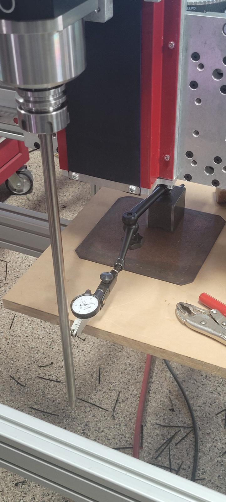
Please ignore the setup you see in the picture, not sure what I was doing at the time. One of the things I found when measuring how square my spindle was to my table. The further the dial indicator was away from the spindle the larger the difference readings if any. Making them easier for me to understand and thus more accurate. The indicator was able to swing the entire width of the table. After I put on a full spoil board I was able to measure the nod of the spindle. This was cheap and easy to do. I used a couple of nuts, a bolt with the head cut off, part of an old bed frame and only one dial indicator.
Current project is making a spindle lockout so I can’t drop the tool out while spinning at 18000rpm. That would make for a very bad day. Design is done and I’m half done with the build. If anyone is interested I’ll share when it’s done. Not sure why that isn’t part of CNCDepots design.
I’m just at the beginning of this journey while also trying to understand the machine I’m going to love to use along the way. Have fun, I am.
There are two things that can be off, the spindle, and the Z axis. Probably many ways to align both, however, if you align the spindle to the axis, that is fine, but how do you know that the axis (the linear rails) are perpendicular to your table in X and Y? The axis itself seems to be the one that all the tramming videos ignore.
I think taking the skim cut after aligning the spindle takes care of the X and Y squareness but I think you might be right, I’ll have to think on that one. Thanks for the reply. What a can of worms we’ve opened. I’ve heard “The answer is out there.” We can only hope.
We might have to rely on how well Avid puts the Z axis together. Thanks a bunch, now you’re making my head hurt. lol
Well, the entire gantry could be leaning forwards or back (“nodding” in metal-mill terms) but I agree there are two results - whether the toolbit is ORIENTED perpendicular to the XY plane, and whether it MOVES perpendicular to the XY plane. I suspect two different types of measurements are required to make sure both are aligned properly - if not oriented right, you’ll be shimming the spindle side of the Z rails, if not moving right, you shim the gantry side (or the gantry itself).
So you might use an indicator on the bit as you move it up and down, AND a precision square between the spoil board and bit.
And this is relevent to me because I flattened my spoilboard yesterday and noticed that my bit is not “flat” when moving along X, so it’s nodded… so there will be measuring and shimming in my future.
Me too I think. One way to check squareness between the Z and X axis would be to mount a dial indicator on the spindle and run it up and down against a machinist square mounted on an a X rail. I think that would work. Does the Avid system take care of the squareness between the X and Y axis assuming you set up the stops correctly? This whole thing a easy on a mill assuming it’s well made because you have the table as a reference surface.
Ya, I was going to use a good square and go up and down like you suggest, or maybe just take my longest endmil and cut a deep square and look at the sides. If there is no constand stairstep to one side in each axis, then its good enough.
Maybe I am a lazy bastard but I didn’t worry about squaring and tramming until the end, in my mind that’s the only time it mattered. I got it fairly close, planned my spoil board (HDPE), mounted my fixture plate and vice. Then got really serious about making sure the spindle was trammed to the plate and the back of the fixed part of the vise. My thought was it didn’t really matter up until that point (within reason of course)
I am cutting aluminum injection molds as well, I have a fixture plate and mod vise from Saunders machine works. I have several working molds at this point, all performing without issue.