Apparently the CNCDepot RM40C is a really popular spindle!
I purchased my AVID PRO back in January and had every intention of waiting for the Smart AV40S spindle right until a RM40C spindle fell into my lap at a price I couldn’t refuse. There were a number of things that made me hesitate and I almost passed it by, however I ended up taking the leap and I’m glad I did.
I had never configured a VFD before, I’d never wired a controller cabinet and frankly a lot of it was daunting, but I was looking forward to seeing how it would turn out. After a lot of YouTube (special thanks to Clough42) and a wonderful chat with @Eric this is what I finally ended up with.
I had a number of goals in mind for assembly:
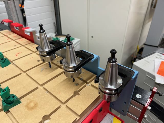
I wanted to be able to perform a push button manual tool change like the AV40S/AV70S spindles as I don’t have a tool rack and don’t know what I want to do with that as of yet.
Having the VFD signaling as an interlock to prevent draw bar release while the spindle was running was an absolute must.
I wanted to be able to turn case pressure on and off manually as well to keep my air compressor from cycling.
I wanted to make sure that the configuration was ready to connect to the CNC12 system so it could perform both draw bar actions as well as case pressure when I fully integrate with the AVID ATC solution, but without committing to something pre-release.
Ultimately this led me to basically scraping the relay configuration inside of the “turnkey” spindle box and rewiring something of my own design. So this is what I ended up with.
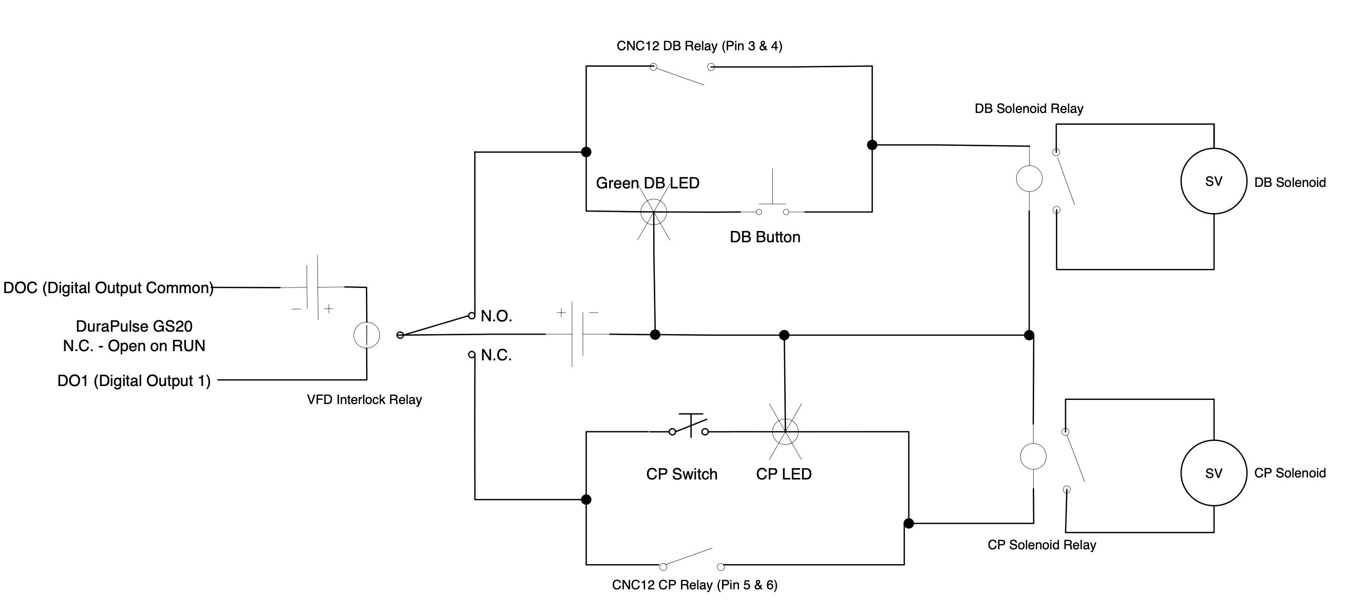
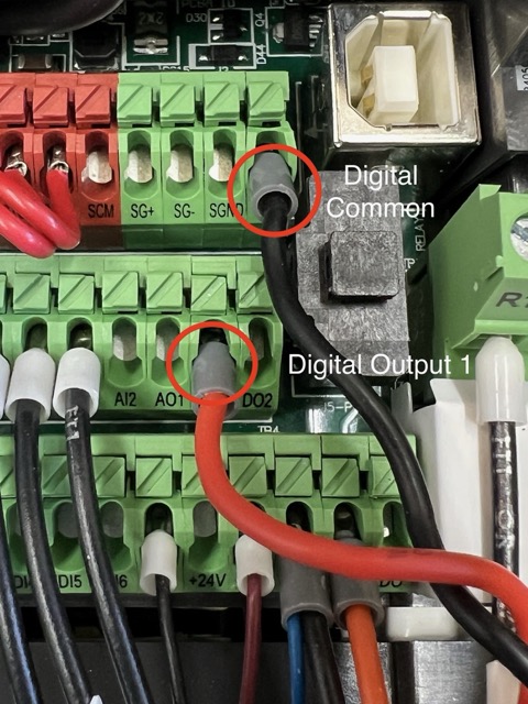
I set the VFD Digital Output 1 to be normally closed and open on RUN. I then wired it to a SPDT relay and did two things, I connected the manual draw bar button on the N.O. side of the relay, and connected the case pressure switch to the N.C. side of the relay.
When the VFD is on but not running, it will close the circuit activating the relay and enabling the draw bar button to be used. As soon as the VFD starts running, it will open the circuit, deactivating the relay and enabling the case pressure switch to be used.
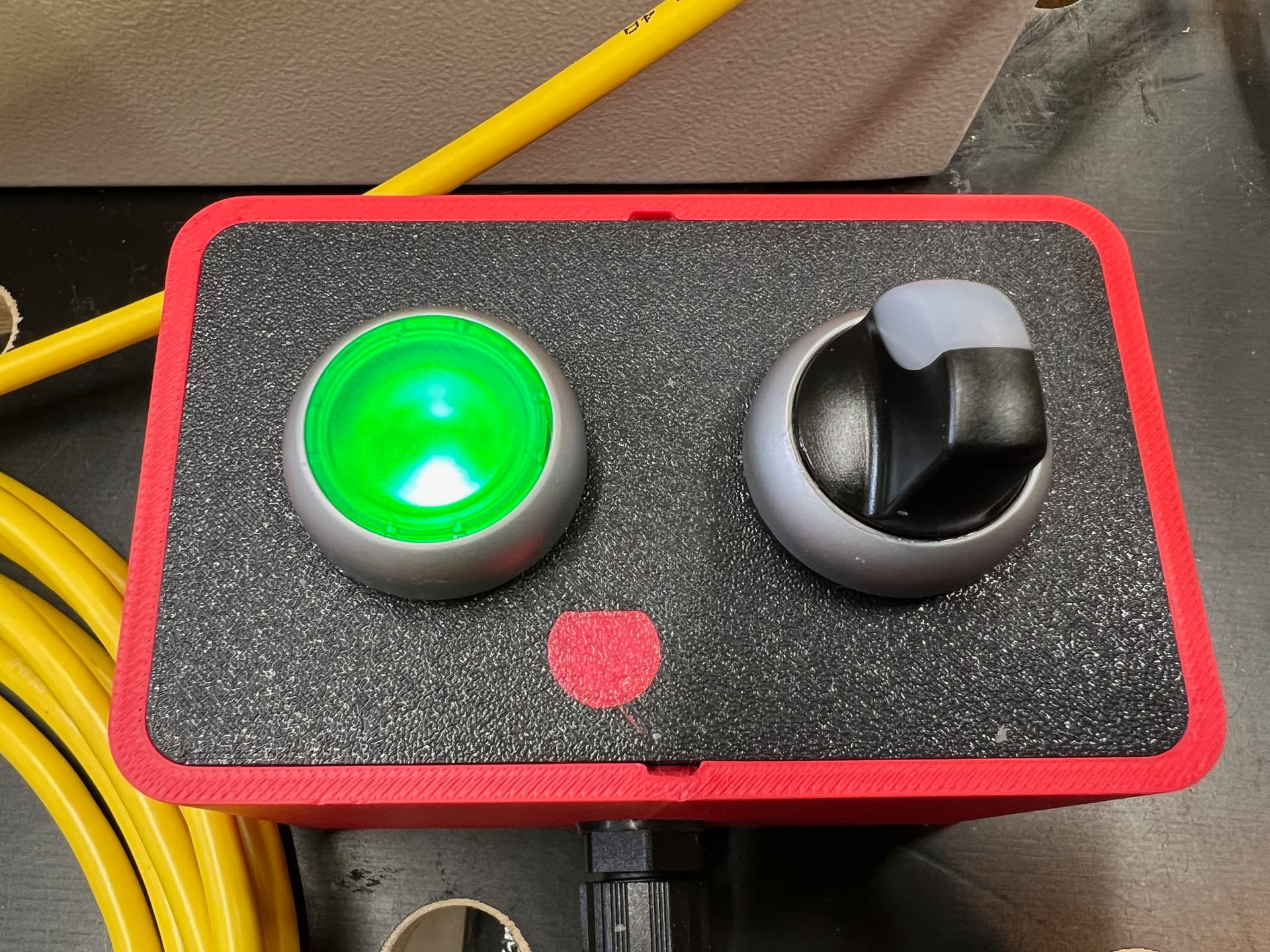
I created a remote control box with a momentary push button and a maintained switch. And because I’m a huge fan of visual indicators, especially with the noise in the shop, I made sure to have appropriate indications for what is happening.
In this case, when the VFD is not running, it will close the N.O. circuit for the draw bar, causing the green light to illuminate, letting me know that I can push the button for a tool change. When the VFD is running the green light will go out and it will no longer be possible for me to do a tool change.
The opposite is true for the case pressure. When the VFD is running, it will allow the N.C. circuit to close and let me choose to turn on the case pressure. When I turn the case pressure switch, it will illuminate letting me know that the case pressure is on. When the VFD is stopped, it will disable the case pressure.
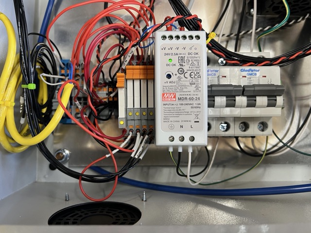
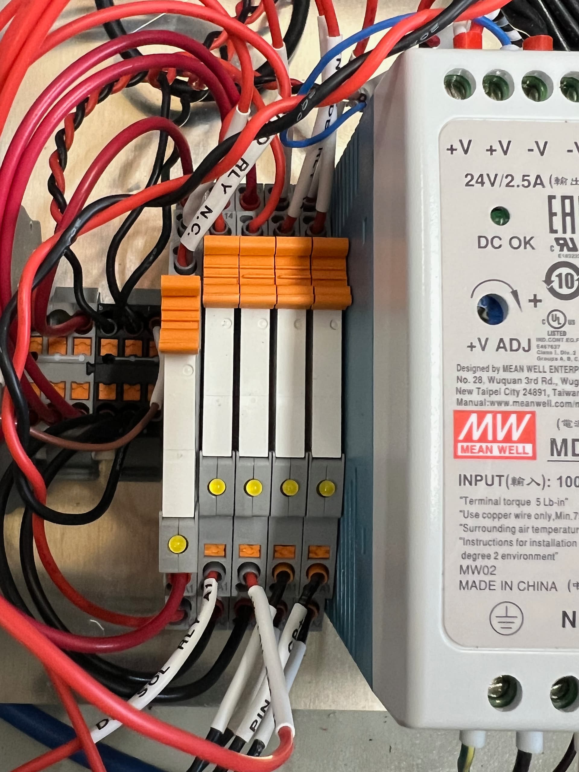
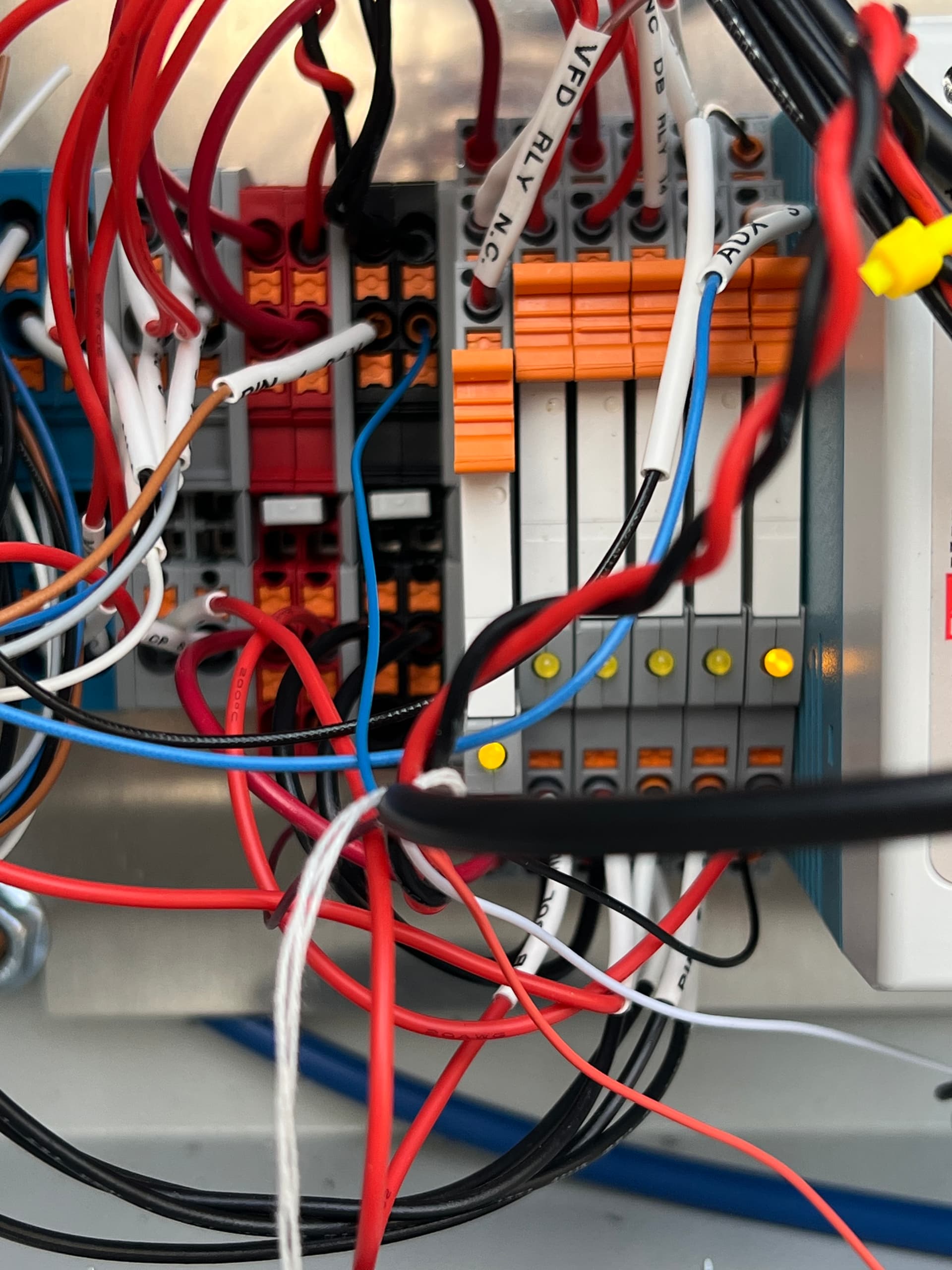
Here is a quick shot of the internal of the cabinet. What started out as only two relays 5V->24V to activate the draw bar solenoid and case pressure solenoid expanded in to 5 relays, 4 terminal blocks and 2 power distribution blocks.
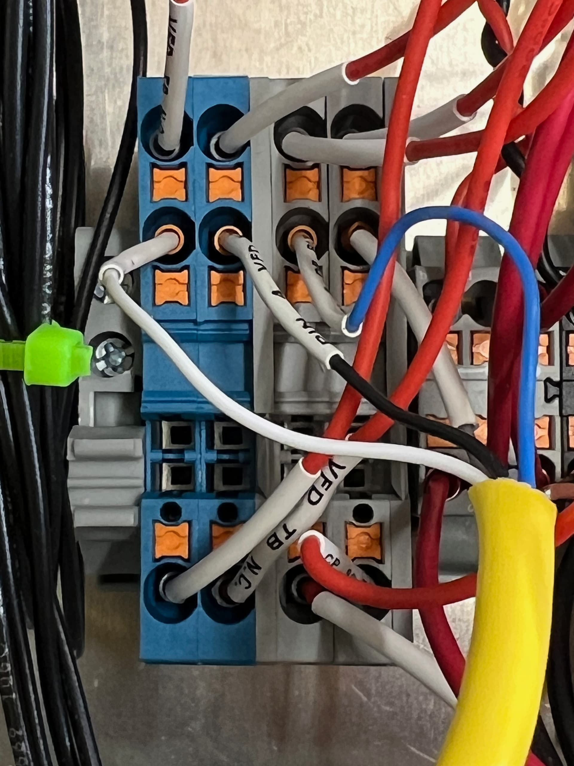
The blue and grey terminal blocks are where I split out and created parallel paths for integrating the external manual control box as well as allowing for the CNC12 to be able to call both. This way once I actually do the full ATC integration, I can still do manual tool changes, or manually turn on the case pressure if I desire, but also be able to have the CNC12 run all of it for me
All the magic is happening here in the relays. The left most relay is the SPDT relay for handling the VFD interlock. This is what allows me to activate the the draw bar when the spindle isn’t running, or turn on the case pressure when the spindle is running. The middle two relays are SPST and are for the draw bar and case pressure solenoids. The combination of the terminal blocks and the VFD relay determines which of these relays activate to turn on one of the two solenoids. Lastly, the right most relays allow for electrical separation between the CNC12 and spindle control boxes and support the integration. When it comes time I can connect the pins on the other side of the 14 Pin cable to allow the CNC12 to do all the work for me.
Again, I really appreciate Eric’s time to help nudge me in some good directions and the pieces of knowledge that I picked up from some of the other forum members, especially Corbin!
cool! I need to add an interlock to my spindle’s drawbar. The problem I have is that the VFD has only one output , and I’m using that for the error status of the VFD into CNC12. How are you doing the VFD error part?
Use your VFD’s Relay as a pilot relay to drive an external relay with more contacts. I used to be a controls/software engineer and this was a very common practice to use to overcome a lack of outputs on a PLC or other devices.
@Corbin - I’m using one of the Digital Outputs on the GS20. And then the GS20 relay sends the VFD ready to the CNC12. What kind of VFD do you have? Does it not have any digital outputs at all or just the single combined relay/DO?
I’ve got the GS10, which I always questioned as being appropriate for my 5HP spindle (Alex said it was, but specs say 3HP at 220 single phase). Luckily power hasn’t ever been an issue, but I had a similar feeling about the “turn key” spindle box not really being turn key at all.
My Digital Output DO1 isn’t being used; I didn’t realize I could use that to drive a relay! What parameter did you set and to what value? I think “P02.16 Multi-function Output 2 (DO1)” set to “1: Indication during RUN”, but if I turn that bit on, the DO1 will be Normally Open and close the relay when RUN status starts. Maybe I’m missing something about it.
Oh wait – I do think I understand it right after looking at your wiring diagram. The VFD interlock relay would activate on RUN. I definitely want to add this in like how you have it, and just turn my case pressurization on when the VFD is set to RUN (currently I use Avid’s Relay 2 for this).
Use your VFD’s Relay as a pilot relay to drive an external relay with more contacts. I used to be a controls/software engineer and this was a very common practice to use to overcome a lack of outputs on a PLC or other devices.
I think I misunderstood how the Digital Output signal could be used; I thought I only could use provided Relay Output directly on the VFD, which is setup only for errors. I thought I had to read the digital output signal and interpret it…but it looks like I can use it to directly drive the relay.
P02.18 - Bit 3 set to 1 for N.C. - Basically add 8 to whatever this value is currently assuming the value is under 7 - I used N.C. as a safety. If the wire is broken or whatever then the DB relay will be in the open position and you can’t accidentally open the draw bar due to a failure while the spindle is running.
DOC directly connected to 24V-
DO1 connected to A2 on SPDT relay
SPDT relay A1 connected to 24V+
Then I use the N.O. for the draw bar. When the spindle isn’t in Run, it closes the VFD digital output which then closes the N.O.
output on the relay allowing the DB relay/solenoid to be activated.
I use the N.C. on the relay for case pressure. When the spindle is running, it opens the digital output which opens the N.O. output disabling the draw bar, but the N.C. output goes back to closed enabling the case pressure.
Make sure the SPDT relay has input protection. Most of the relays I looked at have an integrated freewheeling diode.
The air pressure sensor feeds into the VFD and if it’s low it causes an emergency stop on the VFD which can only be reset by power cycling the box or opening the box and resetting the error.
Given where I have my control boxes, this is super inconvenient if I forget to start up the air compressor or I power the spindle control box too soon before the air pressure comes up to 90PSI.
So I decided to add a new M12 and relay and have the pressure monitor feed the status over to the EX controller. I still have it configured to stop on low air, but it’s way easier to reset if I forget something.
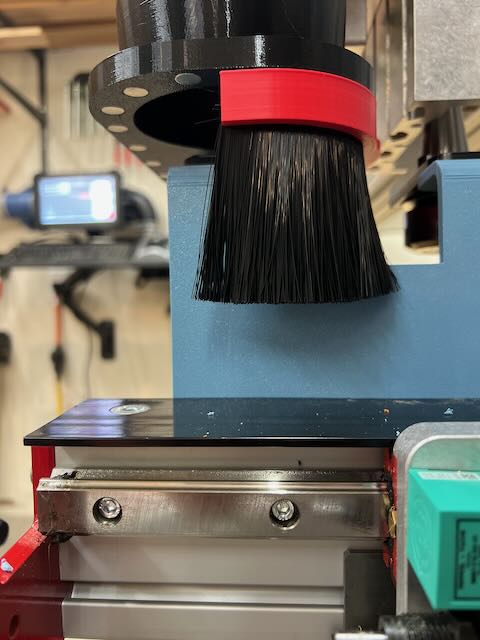
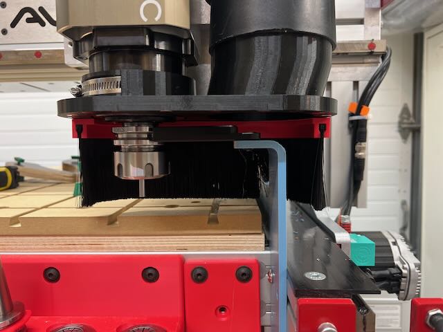
I’m super happy with the spindle in general. It’s so quiet and such a piece of cake to swap tools.
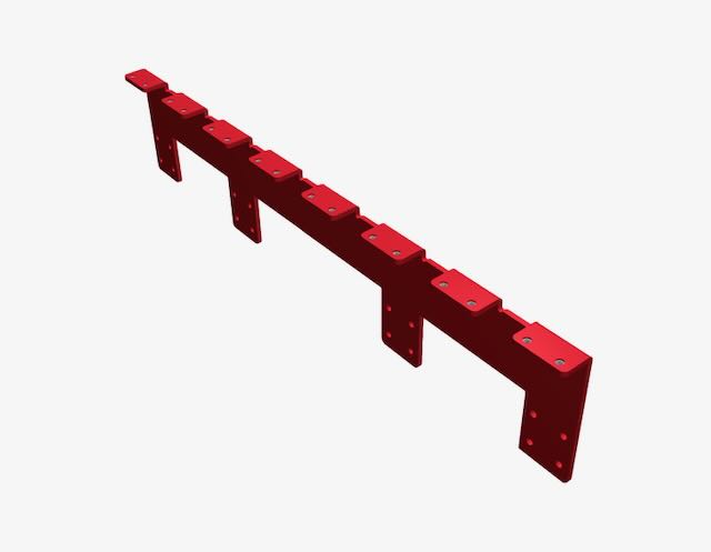
Now I’m struggling with waiting until AVID comes out with their pneumatic tool rack or putting in my own rack.
For grins I modeled up a rack in fusion and did a 3D printed mock up. I already have it in my SendCutSend account, but I’ve been hesitant to pull the trigger yet waiting to see what AVID is going to do.
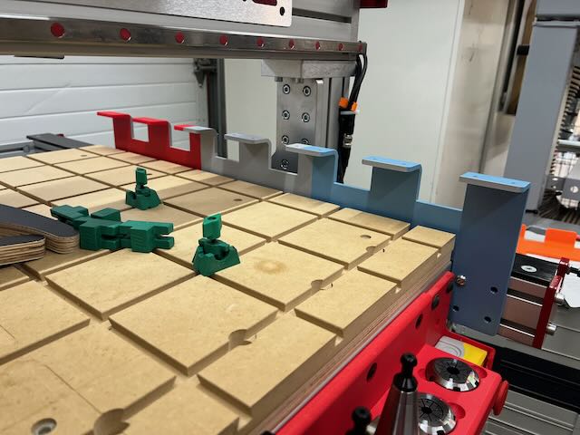
How do you like that Microjig setup spoilboard? Im on the verge of getting rid of my T-track and doing the same thing. I have all the stuff, just need time.
I went back and forth on a lot of spoil board options and finally decided on this one because it’s easy to make my own clamping tooling, it’s quick to remake it once I’ve destroyed it, and I can have Home Depot precut what I need and throw it in the car to bring it home.
My AVID is 5’ wide and 3’ deep. I have a 60x30 sheet of 18mm baltic birch as a base with threaded inserts on the underside. I then have HomeDepot cut a 4x8 sheet of 3/4 MDF into 4@ 2x4 sheets, I cut them on my saw to 30x20 and screw them into the BB base. From there I have a set of operations that I run to cut dog holes, make the relief cuts for the dovetail bit and cut in the dovetails. Including the time that it takes me to go to Home Depot I can have a new spoil board ready in less than 2 hours.
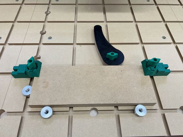
Just as an example, here’s a home made cam clamp with MicroJig hardware, combined with two of their hold downs and some bench dogs.