Amongst all the projects I undertake for friends and neighbors, eventually, I do get time in to knock out projects for myself here and there. A year or so after I picked up the plasma cutter, I found myself wanting to fold up sheet metal boxes, but sheet metal boxes from material that was often thicker (16Ga, 12Ga or even 10Ga) than my poor little sheet metal break wanted to handle. I’ve got a small break that fits into the hydraulic press but that is rather limited in range / access. From there over a couple weekends it seemed like I should just make a little machine to partially scribe through (score/grind) through a plate of a given thickness.
I dessigned and built the following using a linear slide assembly (eBay from years prior) at the heart of it.
I have a cheap air grinder with thin enough cut off wheels to make an effective way to slice, abrasively, through a steel plate, I just needed an adjustable way to control / move it in 3-D space along straight lines at a known depth.
I started by making some simple adjustable legs from 3/8-16 steel rod. This is a large step up from old school ‘all-thread’, althrough that would have worked in this application as well.
A quick clean up on the belt grinder and these ‘legs’ were ready to go…
One of the only parts I had to order for this project, I bought some 2-in diameter UHMWPE to make the feet from. I had this in 4in and 6in, but didn’t want to make that much swarf/waste by turning down so much material.
After a quick parting operation on the verticle band saw, I cleaned up the faces on the lathe and then manually tapped it on the lathe as well.
As far as quick and simple feet for a project go, … this went super fast/smoothly.
So why am I sharing this project where I normally share the projects I do with the AVIDcnc? Well, right in the middle of this, the key piece for this design, I used the AVIDcnc to hack a set of 4 parts from 3/16 steel plate to mount the linear bearing slide assembly to the mounting legs.
Just to make things faster, I stuck to simple flat pattern CAD work in my legacy CAD system. From that I generated some G-Code. This was back in the day before I had written a few programs to auto parse the G-Code output from my CAD system so there is a good amount of hand editing that went on. I am so very glad those days are behind me.

The water level in the plasma tank was pretty low. I am better about keeping it set right now. This was also before I had learned about using Sodium-Nitrate to keep down the rust in the tank so the exposed slats were picking up a good scaling of rust/corrosion.
This was after I had added the parallax adjusted laser cross hairs to the plasma torch though (showing in the photo) which makes finding / setting X0-Y0 so very fast / easy as well as dialing in the edge of material square. You can read about that mod to the AVIDcnc on this forum, here: Laser Alignment for the Plasma Cutter
And the fun part…
The photo below tells the story, these parts just turned out great!
Back in the day I captured this small video clip, real time, of the cut in process. Sorry for my neighbor and I talking in the background on this one, we were pretty tired as the time stamp on the old photos/video tells me we were cutting this around 12:50am… ![]() Plasma Cutting Video
Plasma Cutting Video ![]() In this video you can also see that it was before I had installed many of the upgrades on my machine, so the UHMWPE water gaurds around the tank hadn’t been installed yet.
In this video you can also see that it was before I had installed many of the upgrades on my machine, so the UHMWPE water gaurds around the tank hadn’t been installed yet.
These parts came out great! Only a small amount of time with the chipping tools was needed. The hammer came from my grandfather and the chipping tool was made from a piee of 2in wide band-saw blad and a return pin from an injecton mold welded up by my neighbor.
I performed a quick check fit on the 0.093in wall, 1in square steel tube that these parts will be mounted on and everything worked out dimensionally just as planned. This is a good snug fit.
I also checked the mounting holes against the linear slide. In the photo you can see that my decision to slot those holes paid off. I was in a hurry when I measured and slotting them was the cheaters way to make things go faster. It paid off because in the photo of the two screws, further back, one is toward the left side of the slot and the other towards the right. ![]() Yes, planning to be a tiny bit sloppy when working in steel pays off once in a while.
Yes, planning to be a tiny bit sloppy when working in steel pays off once in a while. ![]()
Next up, I switched over and designed and 3D printed a simple holder to mount the air tool to the linear slide. I also considered fabricating this on the plasma cutter, but 3D printing really was the right choice here. If I were doing it over, I might go with a combination of plasma cut/folded steel and 3D printed liner.
I’ve been using these heat staked (designed for ultrasonic insertion in injection molded parts) brass thread inserts for ~25years in 3D prints and they really do work exceedingly well.
I’ve got a Yardley heat stake inserter that mounts into the drill press and it does a great job. Over all the years I’ve never replaced the heating elements, although I have worn out a few pair of insertion tips.
A quick fit-check on the linear slide…
Next up it was time to finish fabrication on the cross frame mounts to tie in the plasm cut pieces with the mounting legs. Mentioned above, this is simple 0.093in wall 1in square tube.
I ended up cutting this on the horzontal band saw (gravity saw) as it was just toooo darn late at night to be out in the garage running the chop saw with neighbors in close proximity.
Grabbed this on the mill and punched some quick holes in it…
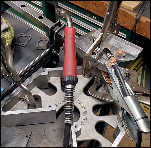
Finally, it was time for some welding… I needed to permenantly attach the plasma cut mounting plates to the 1-in square tube. A good part of this was about getting everything clamped in extra snug so things wouldn’t pull / twist (much) during welding.
That first setup is all-important. For this work, once it was clamped in place with some extra spacers inserted, I blasted in the welds wtih MIG. Way over-kill for this project, but it was fast / easy.
In this next image the reader can see some of the extra spacers I stacked in there to make sure when the welds closed up there will still be enough room to insert the slide mechanism. I didn’t capture it in these photos, but one of the last steps before pulling the trigger on the MIG welder was to throw an aluminum silicate woven welding blanket over the linear slides to protect them from any possible splatter / BBs.
Extra heavy welds, both top and bottom, but these came out great and I count it as a win as nothing warped too badly.
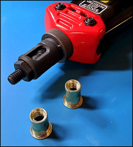
The holes in the 1in square steel tube are sized for 3/8-16 steel Riv-Nuts to interface with the mounting legs.
It takes a decent amount of force to insert / crush these down, in steel.
And lastly a little quality time spent doing the rattle can dance,
And then some plastic end caps where hammered in… I use these on lots of projects. Sure it is kind of cheating but it is a LOT faster than welding up the ends and hides, instantly, lots of shar corners.
The machine turned out great. It is a little finicy to get it dialed in. I tend to just set it up on my welding table (known flat) so that the slicing wheel drags ever so lightly across the full length of engagement, and then if I am going to split say 16Ga plate for folding, I just turn each leg 1/2 a turn. 1/2 turn on 3/18-16 rod gives 0.03125in which splits 16-Ga plate in 1/2 and makes it easy to fold. Slicing and folding makes thin metal like this soooo very much easier to weld up rather than attaching two seperate pieces that will want to warp/pull.
Above, the full machine assembled. I’ve used it on a handful of projects now. It isn’t something that gets used every day, but often, since I’ve got it, it becomes the right tool for the job and I can design in a little thicker metal for strength knowing this will make the bending process easier…
I don’t know if anyone else will get any ideas from this, this is just one way I put the AVIDcnc to work for me.
-Kenneth


