Here a little more than a year ago I was working with some 4-ft pieces of extremely heavy wall extruded aluminum tube. With a 1in wall thickness, the material needed to be supported out beyond the edge of the drill press table. At the time I used a table saw adjustable outfeed roller.
The problem that this project presented is that in between each set of operations, the table height had to be cranked up/down to facilitate usage of center drills, pilot drills, larger silver & Demming reduced shank drills, a counter sink, and a Tapmatic reversing tapping head. Given that this project presented 512 holes though 1in aluminum that all needed all of these operations, the table height and outfeed support kept needing to change.
It would have been easier to turn some tool extensions on the lathe, but this is the solution I went with instead.
I took a small amount of time and extruded some basic shapes in CAD to get a feel for how things needed to line up.

With this in hand a bunch of the parts were flat patterned out and faster than one might susupect it was down to the AVIDcnc plasma table to cut out some parts. This first batch of parts were cut from 3/8in plate.

I struggled a bit with this cut as I was using consumables way, … way past their expiration date. This left quit a bit of slag and took longer to pierce on each hole than it should have, leaving extra top side slag. In the photo, below, you can see that the excessive top side slag snagged the torch and I scrapped on of the parts, all for saving some $$$ on consumables.

Some time was invested on the belt grinder getting rid of the typical plasma draft angles on a few of the parts that needed it.

This project has quite a few holes tapped to 1/2-13 in all this 3/8in plate. The tapmatic just makes such quick work of that.

These are the parts that will make up the “table” part of the sliding outrigger. I used the plasma to locate a bunch of precision pierce holes that I opened up to 1/4in on the drill press. I dropped 1/2-20 bolts through these to keep things lined up during welding (like alignment pins).

A quick mockup, below ensured everything was going to align properly. The huge gap along the back is actually weld prep to increase the surface area of the weld and give the best possible welds.

From the photo, above, the bottom sections were welded up first. My neighbor dropped in these first welds for me. As you can see the design has a 1/4in wide step around the middle perhipery of the pocket explicitly for the purpose of welding in the intermediate plate. This worked out better than I expected.

After that first set of welds down in those pockets, I took over and did all of the rest of the welding on this project. The first shot below shows one of many setups used.

Wetted in on both sides? … Check! I’ll take that to the bank. Welding assemblies of 3/8in plate, this was punched up pretty hot and the travel speed was pretty quick.

I had also put heavy 3/16~1/4in weld prep on some of the outward facing pieces knowing that I would weld them solid and grind them back. In a few of the corners I had to go back and spend a little quality time with a flat file. This was more of a cosmetic operation as there in a decent amount of clearance in the t-slots by design.

So far, so good… In the photo below, you can see how things looked after some quality time was spent on the belt grinder. At this point in the project I was grinning.

A tiny side project, I modified a strap clamp from 3/8in hardware to work with 1/2in hardware and used it to check spacing through-out the project. Everything was great!


Everything was going well, but I decided to go for a tiny bit of over kill and I dialed this part in on the mill and took extremely light skim cuts to ensure everything was fully square/flat/parallel. These had already been through the belt grinder by hand so the worst side only required 0.030in of cleanup. Not the worst for a weldment.


On another weekend while running a set of parts for one of my neighbors on the plasma table, I knocked out a small set of parts that get welded inside this assembly. These will become attachment points.
If I had modeled this part into CAD then the following pices would be unnecessary. I was originally going to weld the support bars directly to the sliding table, but I decided I wanted them to be removable so an audible was called.


One set of these had 5/16-18 nuts welded behind each of the 4-holes to make fixture points and were then welded in place on the assembly. The image below shows one of the two welded in place with its mating component bolted to it. The mating component will later be welded to the supporting / sliding bars.

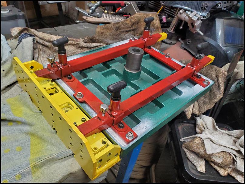
Everything was then mocked up and clamped square to get some proportions. While things were clamped up, the sliding bars were welded to the attachment plates shown above.
It is worth noticing here, there are 1" spacers on the far side of the megasquares between them and the far sliding rail. Doing this allows me to swap in thinner spacers later as the tubing that these slide in is added to the assembly and I am still able to use the same fixturing method to bring everything back into square.

Next up, those tubes, mentioned above, that this assembly will slide back and forth in were cut. I did these on the vertical band saw as i wanted an angle that is much steeper than can easily be achieved on the chop saw…

To go with this, some straps where needed to to attach this to the mounting bars on the bottom of the drill press table… Yup, Once again, a quick CAD 2D outline, some G-Code and it was back to the AVIDcnc plasma cutter.


These parts came out great. This photo was snapped after only minimal clean-up on the slack belt portion of the belt grinder. Only takes a bit over a minute to clean each of these up.

Next up, I took some off-cuts of 1in and 1&1/4in square tubing and welded up a super simple bending fixture for these. In the photo below you can see it in use in the bench vice. Simply load in a part and crank the vise closed on it.

The parts come out looking like below… They are not perfect, but the design allows for this as these will be welded in place and I’ll match drill the mounting holes. Yes, there was a much eaiser way to do this, but this is the way I went about it.

I needed a few miscellaneous parts to complete the assembly. I could have just welded in another set of nuts for the locking clamps, however I wanted to put in a heavier weld, and heavier welds ‘can’ destroy a nut leading to the need to grind off and start over. I decided to simply knock out a set of nuts that are able to sustain a higher thermal load during welding. Sooo, … Yup, you guessed it, back to the AVIDcnc to knock these out.


Wow did these ever come out clean. If one looks close in the next photo, you can see the dark line/ring offset inboard about 0.050in from the top edge of the part. The is the extent of the discoloration due to the HAZ. These parts had no dross and did not need to be cleaned up on the top or sides, and only the tiniest amount on the bottom which came right off with a few taps of the chipping hammer.

Here, a closeup of one of these clamping bolts welded on, next to a commercially made weld-on spring loaded plunger. The spring loaded plunger gives a positive lock to hold the slide out table retracted when not in use (so that it doesn’t rattle) and also picks up on a set of holes near full extension so that one doesn’t accidentally over-extend it and drop it to the floor.

The project was designed so that after fabricating it could be shimmed to be exactly flat to the existing table. I assembled everything and took a quick reading.


You betcha, right back to the AVIDcnc plasma table to knock out the thicker 1/4in part of the shims and then an additional 0.012in shim was cut by hand with shears from brass shim stock.


Next up everything was dissasembled and powdercoated…


One last look from the bottom of the assembly before everything is torqued down and the table assembly moved back to the drill press…
And here we got the outrigger in use.


The outrigger is not fully extended in the photo above. Full extension is 30-inches. Taking the time to have all the 1/2-13 mounting points to clamp things to vertically for end-work on the drill press and the mix of 1/2-13 threaded holes and t-slots in the top surface provision for many, many future opportunities.
Not saying anyone else should do this, this is just what I did and I’m reasonably pleased with it. The design is such that I can release the spring-loaded over extension catches and slip the outrigger in from the opposite side of the table. Were I doing this project over, I would double up this design and make one for each side, offset that slide into/between each other underneath the drill press table.