I just decided to take the plunge and get a full-size CNC. My use is to drop sheets on it and get perfectly indexable tabs and slots to assemble simple shapes for my business, for starters. I’ve used Fusion for a while for 3d printing, but I still haven’t broken out of being a novice. I do understand simple issues with using a CNC router for tab n slot, like rounded corners and needing to dogbone. However, I’ve read that a tolerance of .007 is appropriate to allow parts to go together. Whenever I watch a video, I try to figure out the workflow for adding this tolerance, but it seems like most of the time it’s left out. I do understand how to offset a cut, but I must be missing something because doing that operation for every single face of a cut seems like I’m doing it the hard way. I was expecting a tool to allow me to join/cut two parts and have just have the cut take a little extra somehow.
The reason I ask here is: am I worried about nothing? Will the cnc not be as precise as I’m afraid, and leave an interference joint that I can just push together with a little bit of mallet?
Do you add the tolerance in the manufacturing/milling part? I think it’s called “radial stock to leave”? Makes me feel better about it, knowing the best practice is just to design the parts to perfection and then make allowances.
No, I do it in the design. If you do it in “radial stock to leave” you can make your entire part smaller… I suppose if it’s only a little that’s an easy way to do it, however I like to be pretty specific about what parts of my model I loosen up for fit.
Hi JJeeps - I’m going to go different than Eric, and recommend you use the “radial stock to leave”. This way you don’t have to change your design for machining tolerances; IMHO, tolerances should be related to the machining operation itself and are easily handled in the toolpath and can vary based on the bit selection. IE: I do dovetails on my CNC, and change the stock to leave on the pins to adjust to adjust the fit. Usually -0.005 to -0.008” stock to leave (negative to cut more).
I have a video where I talk about this with regards to straight deep inlays; you might find it helpful!
Although, I should also mention: if you are doing flat-pack style furniture, like what Eric is doing, then his method will be better…because you want to simply do a profile in one pass, and only change dimensions on specific areas of the profile.
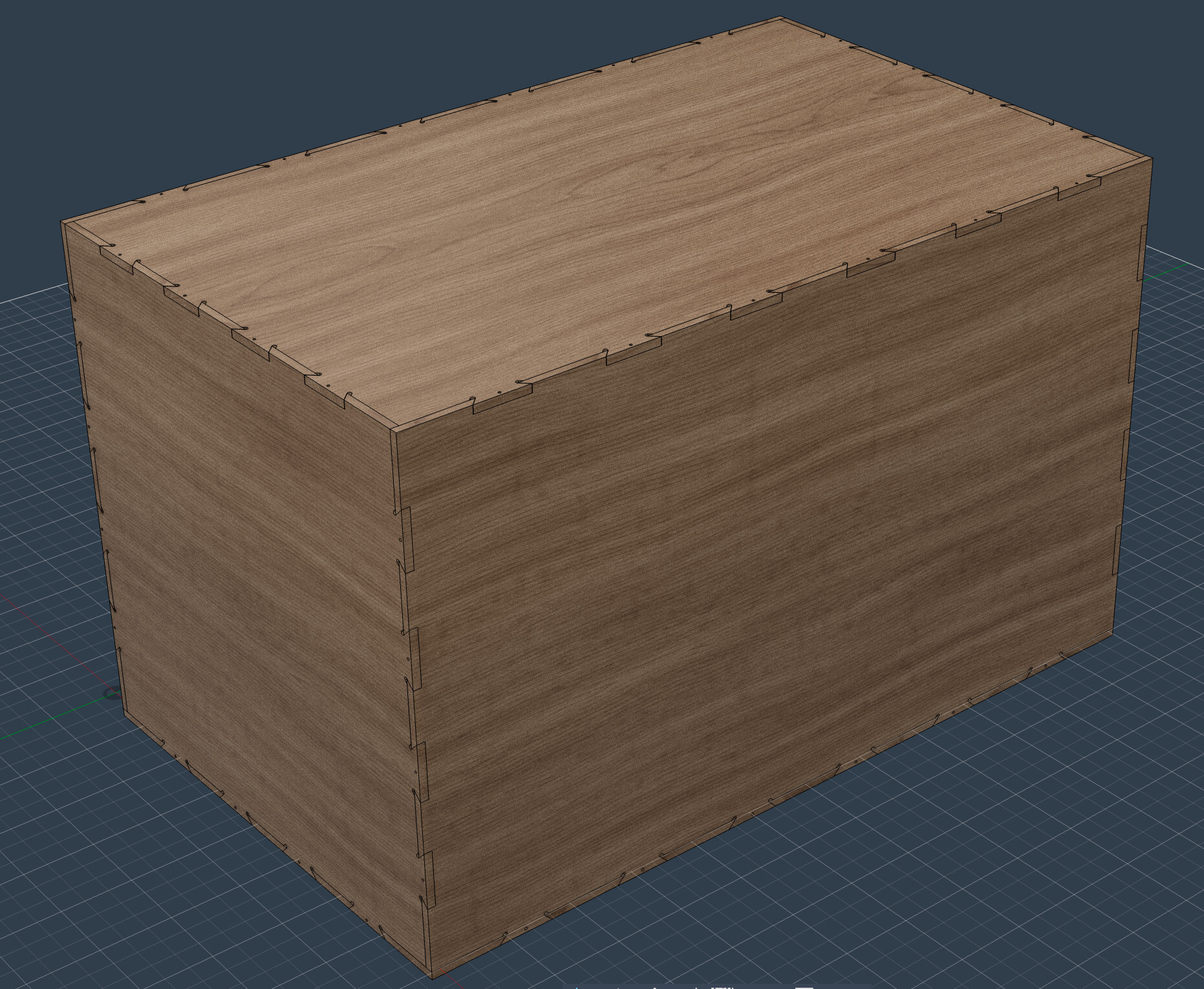
These are actually pretty cool, they are dovetailed lock together crates that are all machined with one single endmill, dovetails too.
The trick with these is that you want the interior dimensions exactly as specified in the model. If you did the “axial stock” trick your interior space would shrink. What I do instead is this:
In the configurations I have an offset for the “male” side of the dovetails. This allows me to precisely control the tolerance. What I shoot for on these is “one good whack with a hammer and it fits snug” and then I use fasteners to hold it together. I even have a looser tolerance for the lid so it’s easier to take off.
This is a pretty specific and nerdy way to do tolerance. The only other place I’ve used this method is cabinetry. You don’t want error stackup on a run of cabinets.
I’ll throw in my two cents from when I did a lot of furniture out of plywood (I guess flat pack style) using Fusion 360.
At the time I would always use a parameter for the plywood thickness and model everything as exact fit. Dados were usually created using boolean cut operations of intersection pieces and left there.
I would use stock to leave on the dado/rabbit operations for fit/glue (-0.008 radial and -0.004 axial). This worked well but I wouldn’t do it that way today.
Note: probably unique to me was I was using the Manufacturing extension (actually back then the nesting extension which has been folded into that today) to do sheet layouts and my parts/design were changing a lot.
When a part or design changed, I would have to re-run a layout study and create new manufacturing models if the design changed significantly, or update an existing manufacturing model if changes were minor. Fusion would frequently lose track of geometry selections in CAM in the later case, and in the new model case you would frequently have to re-select geometry.
Even though I would reuse the existing tool paths through copy/paste, I would have to select geometry again and make sure I was using the correct one (e.g. one with stock to leave for dados, one for exact cuts other places). I spent so much time doing this over and over again and often would make mistakes.
If I were to do that type of work again today, I would model in all the gaps using parameters in the design as suggested above, and leave CAM to cut pieces as they are modeled. It would be far less error prone and create simpler and likely more optimized cut operations.
This is kind of the conclusion I came to on this stuff… You can do “toolpath tricks” but as you said some of those get wiped out when you have to recalculate.
It’s easier if you’re running the same model over and over again, but if you put it away for a period of time and come back later I often would forget where the tolerance and the “toolpath tricks” were.
You can also… sometimes model something so that plywood thickness changes don’t effect anything.
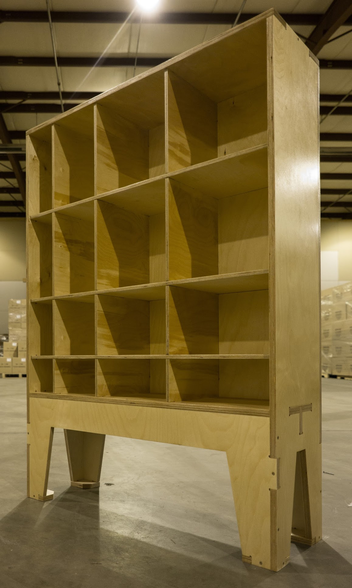
There was a time period where I was making tons of these:
The joins on the original design were tied to plywood thickness and it was a nightmare trying to make 5-10 of these at one time.
I ended up re-working the entire design so that all of the fitted joints only rely on profile cuts, on in otherwords ONLY edges that you machine. This means that you have precise control over the fit and you don’t have to recalculate for each plywood thickness change… You can even mix and match plywood thicknesses too.
PS that file is a free download if anyone wants to make one.
Not to open a whole different can of worms, but if I’m creating panel grids of various flavors, should I just invest in a purpose-made product that plops the stuff on the screen and automatically fills in more basic joinery like dadoes or rabbits? I was excited about tab and slot, but I’m not sure if my limited selection skills are up to modifying every face of every feature lol. I’ve started watching too many videos with people just clicking and dragging fully joined models right out of the cad.


")