In case it is useful I thought I’d share some of the stuff I learned the hard way instead of reading the directions.
First I’d like to thank @corbin and @Eric. In particular Cobin’s software made it possible for me to get everything working. I’m also using the 3d printed dust boot he designed. Pretty much everything I’m about to say was already found in the instructions they wrote, but since I missed it, I thought others might also.
Basic Wiring
The spindle I bought needed 24V in the M23 connector for the cooling fan. I ended up adding a 24V power supply to the din rail in the spindle control box. At least on my delta VFD I was able to get access to the signal for my spindle being on, and connect that to a relay to control the cooling fan. I also sent output of the relay along with 24V power to a separate control box where I had my pneumatics.
In the pneumatic control box I added a relay to make sure the drawbar never released while the spindle was still on. I think this was recommended in the instructions, but it wasn’t super clear where to get the signal from.
Dust boot
When using Corbin’s dust boot with the dust host facing the Ymin side of your machine, you must have your tool forks pointed to the Ymax side of the machine. I didn’t do this at first and the spindle would wedge the bristles from the dust boot into the forks. Then it would pull the tool back out of the fork when moving away.
Using the dust boot you need a little less than 5 inches between tools. I’ve played around a little bit with designing either a pneumatic dust boot or one controlled by an independent esp32 with a stepper motor. However given the geometry of the spindle it looks like the absolute minimum is around 3.5 inches. For me at least I decided it wasn’t worth it for a single row of tool holders. Though I may revisit in the future since I like a challenge.
If you use thin superglue to attach your magnets to the dust shroud, give it a whole 24 hours to dry. I thought things were plenty dry after just an hour or so, but the next day my magnets were glues to each other, and not just the dust boot.
Tool Holders
Don’t try to use 3d printed stands for your forks. I saw the warning, and thought I’d be ok if I just used a slow feed rate and threw some extra perimiters on there. Unfortunately things would only work for around 10 tool changes before the stand broke. I tried experiments with orientation of the layer lines and flavors of PETG instead of PLA. While I don’t double that someone might crack the code, just making one out of a 2x4 really seems to work better.
I tried some experiments with “hole” style tool holders. It proved to be super hard to get dialed in. You really more than just an indentation in your spoilboard to hold the tool. It is extremely hard to get the z height set properly with something as rigid as your spoilboard. You also want to avoid the tools getting out of position from vibrations while your machine is in use. I tried a 3d printed slightly conical holder, but it also kept getting crushed during tool changes. Perhaps something with magnets and springs would work, but I ended up with the more standard fork style holder.
Thanks again for the help of this community, everything seems to be working great.
You are using Centroid or Mach 4? I figure it is Centroid / EX controller, right?
What spindle did you get?
How did you add the extra relay in to ensure the drawbar isn’t released? I noted in my directions that it would be good to do, but I didn’t write how to do it because I haven’t done it.
I was figuring the best way is to have the VFD control an interlock relay that is closed when the VFD is not spinning the spindle. However, my Automation Direct VFD only has one programmable output, and it is being used by the EX controller for “VFD is ready” state.
I’ve been wanting to test out “hole” style pockets…I just haven’t gotten to it yet. I hear it can work. One slick thing you can do is have the holder held onto your spoilboard recessed with magnets, and pop them off when you need additional space. Pwn cnc has a 3d printed design and I want to try something similar: Tool Rack – PwnCNC
Yes I’m using centroid now. I’m pretty happy with it so far. Writing lua scripts for mach 4 always felt like I was a little short on documentation and just trying commands to see how things really worked.
I got what appears to be the next version of the RM40 from CNCdepot, and so far I’m really happy with it. I don’t really know how different it is from the previous version, but I am happy that its’ runout is less than I can measure with my no-name dial indicator. So far things are working great, although I’m a little worried about if dust will interfere with the spindle / toolholder interface over time. Perhaps I need to fabricate some kind of cover for my tool rack.
It sounds like we might have the same VFD. Mine also has just one output which seems to be used by the ex as well. It would have been great to use the zero motion signal.
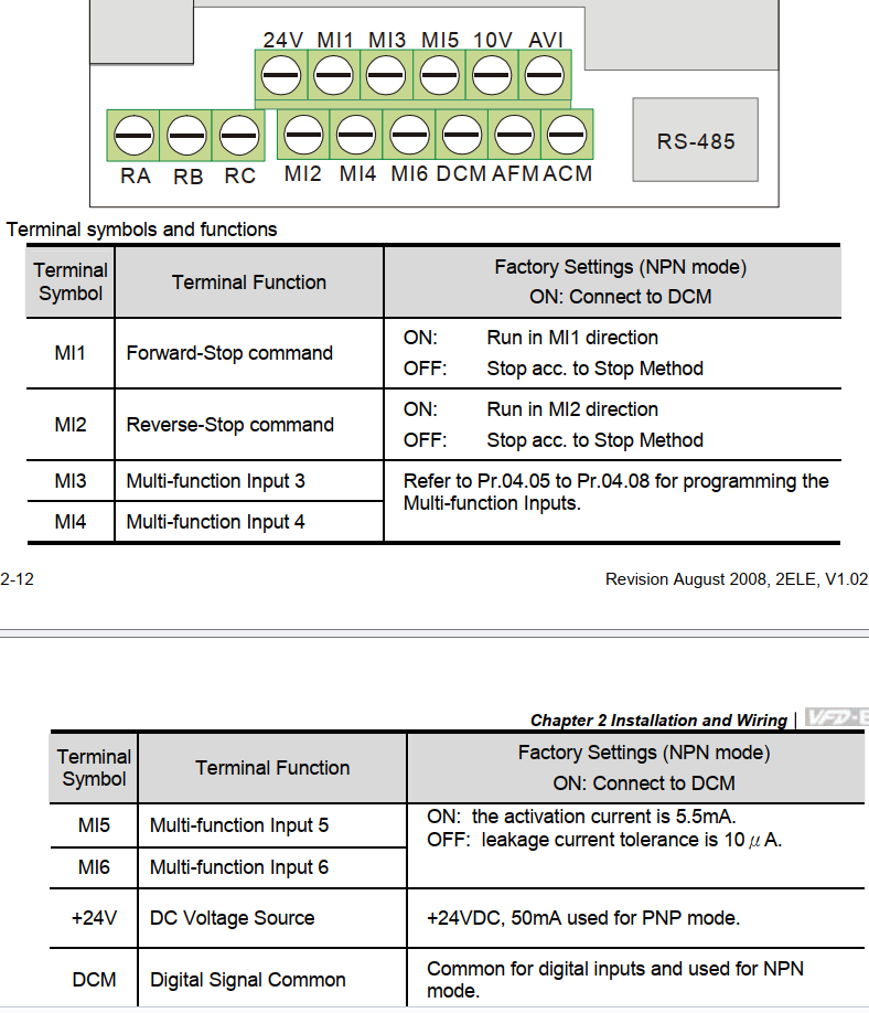
What I did was use the 24V and DCM pins to power a 24 volt relay. Then I connected the M1 pin as the signal. The relay inside the VFD box both supplies 24V to my spindle’s fan when it is running, and connects to a different relay in the box with my pneumatics. That one break the connection to the drawbar solenoid when the spindle is running so hopefully I’ll avoid doing something stupid. I’m a little worried there is a window after the spindle is commanded to stop before it actually stops rotating, but as you mentioned there doesn’t appear to be a way to get a signal it is completely stopped.
I guess if I ever add support for my spindle to go in reverse I’ll also need to modify things.
The part about the y-minus orientation being in the video is absolutely true. And yet somehow I made the mistake anyway.
I suspect a combination of z-axis independent dust boot and hole style tool holders would be the most efficient use of space. However I already have enough holders for my most commonly used tools so it really would be premature optimization for me to increase the density at this point. Then again this whole project is for fun anyway.
I’ve been pondering if it makes sense to use the tool height setter to make sure the tool has actually been loaded successfully after every change. Do you think that is a good idea? I’m not really worried about the spindle milling air because nothing is loaded. But it just generally seems like a good idea to try and detect if things failed.
You both have mentioned, IIRC, to not use 3d printed forks:
I don’t have my ATC compatible spindle yet, however, I have a formlabs SLA printer (absolutely awesome) and have been using Tough 1500 resin for some parts. It can be quite strong and still flexible as needed. I’m not experienced with PLA/PETG printers, but maybe this could work better?
I’d be happy to print off and send a prototype if anyone wants to evaluate the material. Just let me know if interested.
My goal is to eventually have a ATC system (new avid spindle) and a large set of “standard” tools (10 or more) available before I have to manually quick change tools.
As a third opinion, all my tool holder stands are 3d printed in PLA. The forks are not, although I’ve printed one to have on hand in emergencies, but the stands are. They work just fine, and act as a “fuse” in case something goes wrong - when I get the code wrong, they break before anything expensive breaks.
I’ve heard FormLabs makes some really good SLA printers! I bet they would be strong enough, but you have to make sure they aren’t brittle; I’m not familiar with SLA resins.
I was mainly experimenting an FFF printer for a 3d printed fork holder from PLA, and the orientation that I printed it at would cause layer separation. I think I could easily solve this by printing it on its side for additional strength, and increasing outer layers.
I didn’t try PETG or ABS or ASA; all those things could make it stronger and less brittle. I think they have good potential.
I do have some PLA forks I printed for holding extra tools that I have on my wall for manual tool changes, but it is a janky design I found somewhere.
They really are amazing machines. The available materials cover the full gamut – from super flexible rubber like materials so strong they are actually used for replacement teeth!. The downside is the resin costs are quite high.
The “default” resin is strong but brittle – definitely not suitable for this. For example, I printed some custom DIN rail mounts and the arms couldn’t flex enough to mount to the rail without breaking.
The “tough 1500” I mentioned results in material like polypropylene, so very strong but still flexible while returning to normal after deflection.
I’ll probably print some forks to house tool holders for manual tool changes and see how they handle.
Super excited to have an ATC capable machine and peeling back one more layer of the CNC onion!
Can I ask which way the layer lines are oriented in this print? I’m also how you fastened the fork to the PLA. Is it a nut / bolt or some kind of threaded insert?
I was also interested in the fusable link idea of it, but as I kept making the holder stronger and the feed rate slower I really started to question its value. I think for me it ended up being mostly cosmetic things like having a giant number on the front.
I don’t really question that this must be a solvable problem with a 3d printed holder, especially since DJ has provided pictures of it working.
Another advantage of the 2x4 method is that I was able to flatten and create the mounting holes with the board already in its final location. That means I know the holder will be exactly parallel to the spindle, and the location was exactly 5 inches apart which made setup easier.
Thanks to all of you for sharing your thoughts and experiments.
I’d guess they are printed on the side; if they are printed upright, the upward force of the tool coming out may rip them apart at the layers. I never tried printing on the side for my design, but I’d bet it would work:
There is a slot in the back to put a 1/4-20 nut. I may look into trying this again out of ASA and side printing.
The wood rack as you noted, has a lot of advantages (and is simple). I wish mine had deeper side areas for the brush; sometimes the brush pushes up a bit on the hood, causing it to flex (and it did crack after a while, but CA has solved that for now!).
For accuracy of placement, one could machine the bottom profile in their spoilboard and get a really accurate position.
It’s printed laying on its back, so the extrusions are continuous from bed to fork. Here’s the STL (0.2mm layers, 0.5mm extrusion width): cnc-tool-bracket-1.stl (129.0 KB)
Attachment is just nuts and bolts.
Reminder: I printed the risers, not the forks. I have a printed fork for emergencies but the ones I use normally are purchased. I don’t want anyone to be confused by the variety of words and think otherwise