I’m totally self-taught / YT taught when it comes to Fusion both the CAD and CAM sides. I’m getting to a point where there are topics that I either struggle to find YT videos or previous discussions on and would really like to pursue more formal training on.
Does anyone have recommendations for programs that I could pursue either on a whole course style of engagement or 1:1 training?
@Eric - This looks like what I’m looking for. Have you heard from anyone who has participated in his classes?
Also as an aside it was seeing your Digitally Fabbed site referenced in another post that inspired me to step up my fusion game. Your work is excellent!
So to give you an idea of what I’m currently playing with. I have a 6yr old who absolutely loves to run around swinging anything stick shaped like a sword. He convinces the Sherwin Williams guys to give him extra paint stirrers so I can “cut them into Leonardo swords” (TMNT) on the bandsaw
So I figured why not take this opportunity to model something that looks like a katana in fusion and carve it out of 3/4” plywood. In the Dan Lee boat building I saw him make a fixture with a square on the left and a boat shape on the right which I assume he took a solid and use the boat shape as a cutting tool out the solid so he could machine and flip. Then I’d assume he sets his WCS to the corner of his fixture and it should be straight forward. Now I don’t know this for sure, but it would make sense to my uneducated mind.
I have this sorta model out of a 80mmx750mm piece of plywood and instead of machining a negative fixture for it, I was thinking it would be clever to use 4 reference pins to flip because pins seem to be all the rage.
I could conceivably mill the whole thing out of an even larger piece of plywood and let the CNC build a perfect 80mm x 750mm blank and then set my WCS off of a corner. But I really wanted to explore other ways of doing WCS references even if my initial blank is 2-5-20mm off from what it should be.
So I was thinking if I were to drill the reference holes in the first set of operations while also milling the top half of the sword, I could flip it, drill the holes into a 3/4 mdf work surface and align with the pins. Then since I’m using 8mm reference pins, I could use an 8mm collet, an 8mm pin in the collet and use that to find the center of one of the reference pin holes and set that as my WCS anchor.
But I’m just spit balling at this point, and this is kind of why I want something a little more in-depth or 1:1 to see where my theoretical non-educated idea actually meet up with the real world
I’m one of those people who starts with a question where the answer then leads to more questions and I worry about a course that only spends 19 mins on setups. The hour on various tool paths does give me some level of hope, but to a certain extent I can just pick a body and try different tool paths and simulate them to see why I might choose one over another.
You are on the right track. The pins locations and the holes in your stock are all that really need to be accurate. The edges of your stock then do not matter much as long as you have enough material. I like to keep tool holes on center line of the stock when possible and keep the same WCS when I flip the material. Two pins in table or tool plate, in the stock one hole and one slot. The hole locates in XY the slot clocks for rotation and allows for some variation in the location of both pins and holes
I was thinking about what that would look like from a Fusion perspective. I could always create the holes in the centerline. However, I assume in fusion then you set the center stock point as your WCS reference as long as the center stock point is collinear to your two pins?
The other question I was mulling over is if you lost your WCS how could you regenerate it. And really as long as you can drill two new pin holes in any work surface with the same distance that are parallel to your machine axis, you could then use a gauge pin like above to reference one of the two points and rebuild your WCS off of it.
The flip operation then would just need to be updated to reference that pin hole for WCS as well.
I begin by cutting two slots for the corner-finding touch plate and setting G55 based on those features before machining the holes. Using two slots allows the EX controller to compensate for any rotation if the jig needs to be repositioned. The alignment slots are located near the center rather than the corners, as corners are more susceptible to damage in my shop and MDF tends to be fragile.
This approach yields fairly good alignment, I think most of the residual error I see (around .02” maybe, varies) comes from tool deflection rather than coordinate system inaccuracies.
Another tip: In your first cut, zero off of the bed and do a facing toolpath to get your stock as close as possible to a height you set in your model. Will increase Z accuracy vs zeroing off the top of the stock.
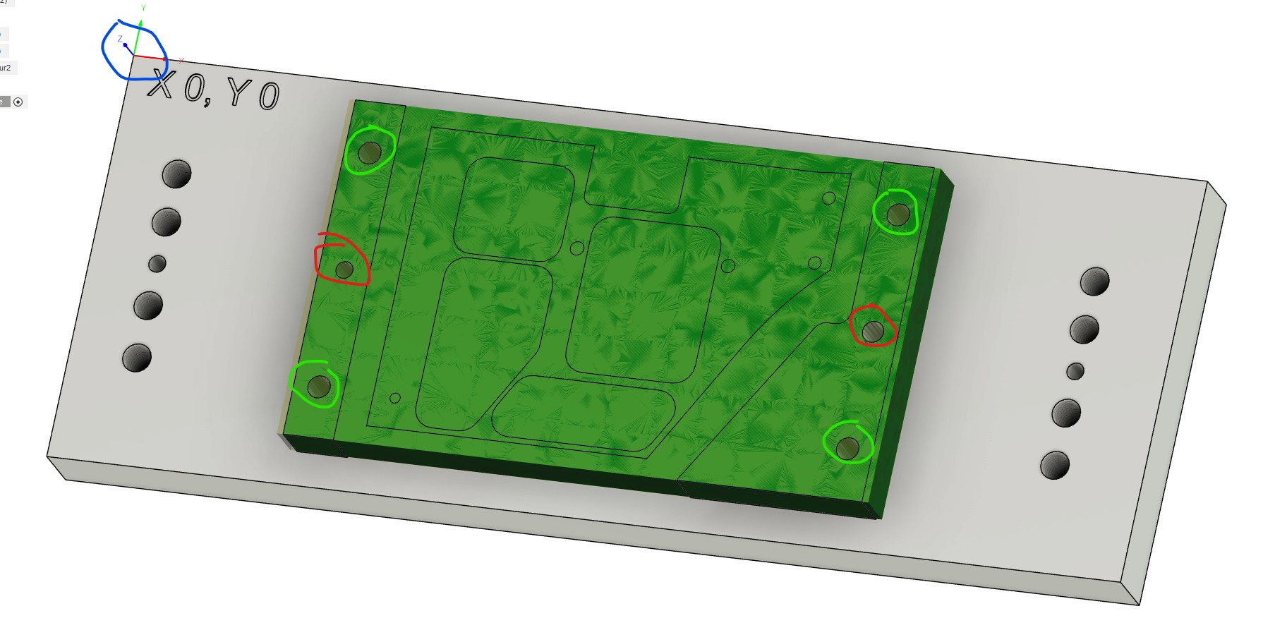
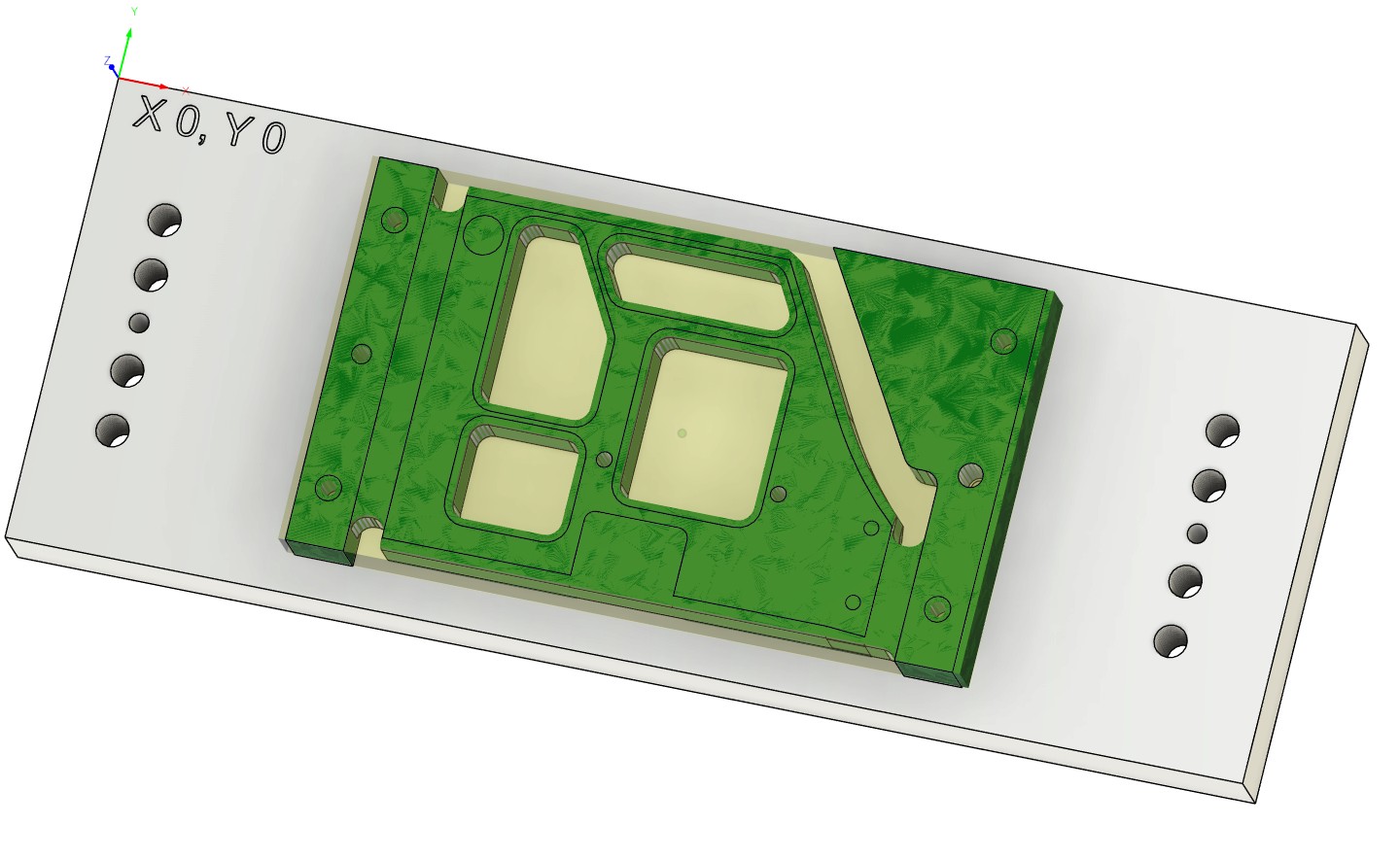
Tooling fixture plate. Blue circle is the WCS home for this fixture. The red circles will have dowels on the LH side and Diamond pins on the RH side. The other holes will be threaded for hold down bolts. Fixture plate will be used to machine three different parts and will do 4 sided machining on two of the three parts.
First op1 in the vise will be to drill the index holes in red and the green hold down holes. Using the corner of the stock for the WCS for this operation. The hole patterns match the fixture plate.
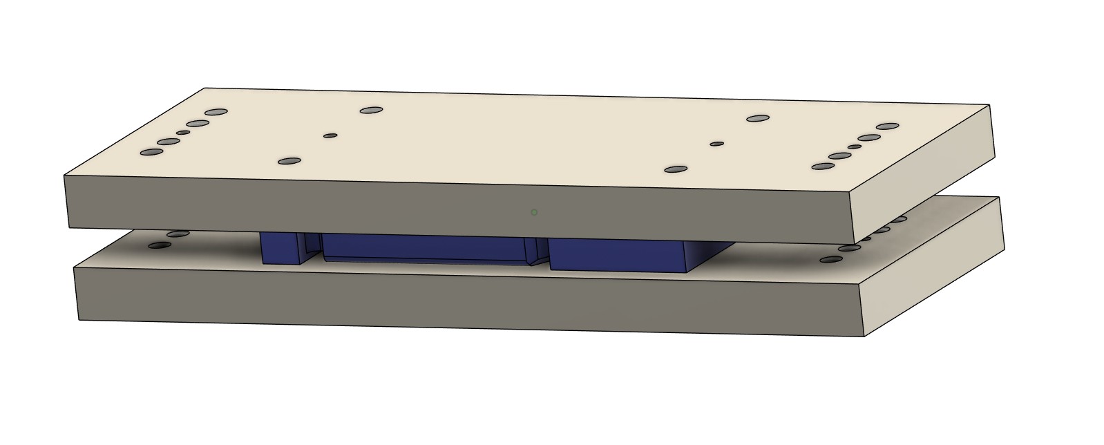
The stock is mounted to the fixture plate indexing of the red holes on the dowel pin and Diamond pin. The blue circled corner of the fixture is the WCS for the operation and was established when making the fixture plate. So I know where the index pins are based on the corner of the tooling plate and I can always find it again off the plate edges/corner.
You could do the same thing without a tool plate and use the spoil board and pin holes in the spoil board. Just move X and Y to a known position. Record that position (I do that in a notebook) and zero that position as your WCS. The fake that WCS location in Fusion with as simple as points in space relative to the tooling hole locations.
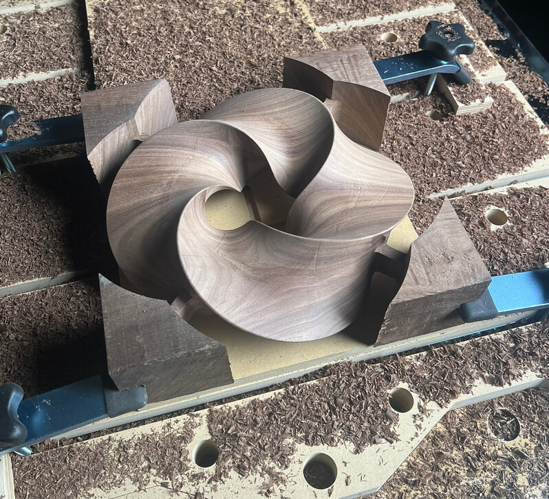
While I’m figuring out next steps with finding some good training I figured I would just go for it based on what I was thinking in my head. So this is what I ended up with.
For side one I did a standard left front corner WCS anchor. And the first machining operation I performed was boring two 8mm holes parallel to the x-axis which would give me a future reference x-axis for the second side.
For side two because I had the x-axis already built into my work piece I decided to get really crazy with Fusion and AVID (Acorn). I used one of the two bore holes as both the WCS anchor as well as point 1 for training the CSR. I then used the second hole as the point two for the CSR and for grins clamped at a really weird angle. It was super cool seeing the EX software rotate the work piece with respect to the CSR.
Angle probing is one of my favorite features for this exact reason. It’s dead simple to drop a jig anywhere on your table, hit two pints and boom: You’ve lined your machine up to the part.
PS, this is how I setup the rotary calibration utility. Your rotary is supposed to be installed parallel to X or Y, but in reality that utility just picks up the angle it’s at. That way if it’s a little out of alignment it doesn’t matter.
I remember seeing it in your touch plate utility video and thinking it was really cool but not really understanding when/why it would work in practice. And then it occurred to me that it would be really useful for what I was trying to do here so I remodeled my alignment holes, not to attach to a stationary reference, but to create this internal reference bound to the part I was building
I’m hoping to add rotary at some point in the future. There are a lot of things I’d love to do with it as well and the peanut bench was very inspiring too!