Here is a project I am currently working on.
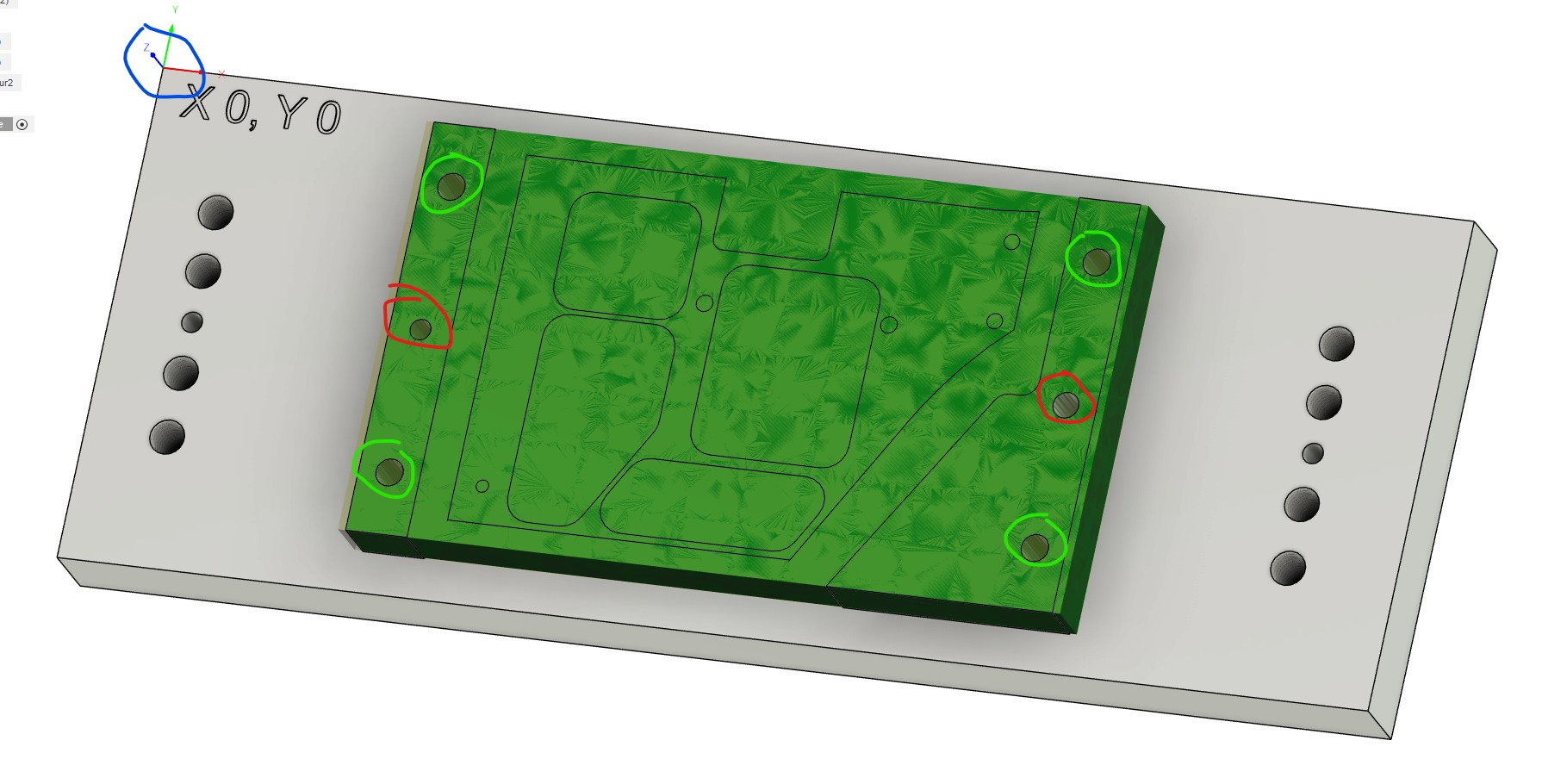
Tooling fixture plate. Blue circle is the WCS home for this fixture. The red circles will have dowels on the LH side and Diamond pins on the RH side. The other holes will be threaded for hold down bolts. Fixture plate will be used to machine three different parts and will do 4 sided machining on two of the three parts.

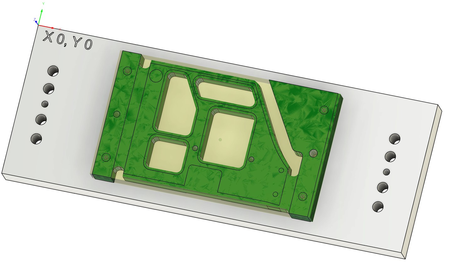
Part Example
First op1 in the vise will be to drill the index holes in red and the green hold down holes. Using the corner of the stock for the WCS for this operation. The hole patterns match the fixture plate.

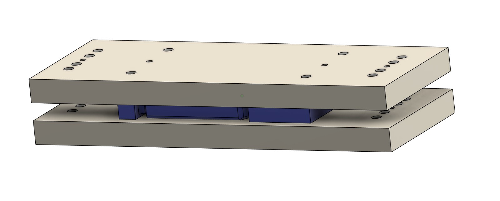
Op2
The stock is mounted to the fixture plate indexing of the red holes on the dowel pin and Diamond pin. The blue circled corner of the fixture is the WCS for the operation and was established when making the fixture plate. So I know where the index pins are based on the corner of the tooling plate and I can always find it again off the plate edges/corner.
Op3
Flip the stock. Keep the same WCS, indexing off the pins/tool holes.
In Fusion I have the tool plate in the model twice, and use them for two setups in CAM and pick the same X),Y) corner on the tool plate.
You could do the same thing without a tool plate and use the spoil board and pin holes in the spoil board. Just move X and Y to a known position. Record that position (I do that in a notebook) and zero that position as your WCS. The fake that WCS location in Fusion with as simple as points in space relative to the tooling hole locations.
Hope that helps.