Afternoon all,
Soooo, installed my PLH3d-XT-50, with the Magnetic Dock and the Adapter Pro over the last 2 weeks…I noticed that in the Adapter Pro connections (printed directions) show connecting PWM to Port 2, 18 and Ground to Port 2, 17…Ive watched everything online or YT, and everyone has Port 3, pin 3 or 4 and the ground, pins 17 to 26…Am i losing my mind ?..jjneeb, you’ve been the saving grace for alot of us…am i losing my mind…? I changed all the pin selections back to your detailed instructions, from your GoogleDrive folders…So got the laser to “armed”, what would be my sequence of operation going forward.?? All software is up to date…Thanks everyone !!!

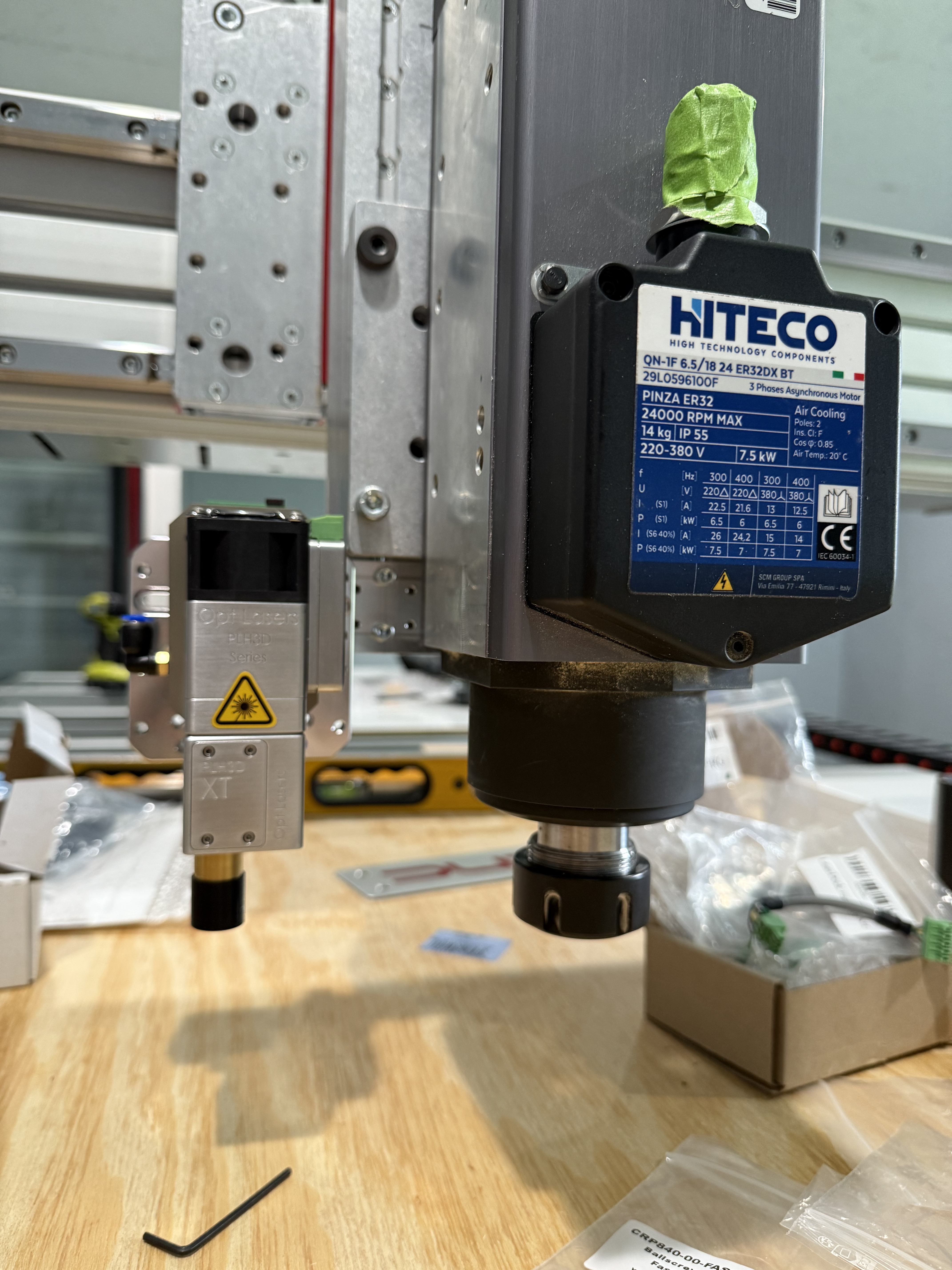
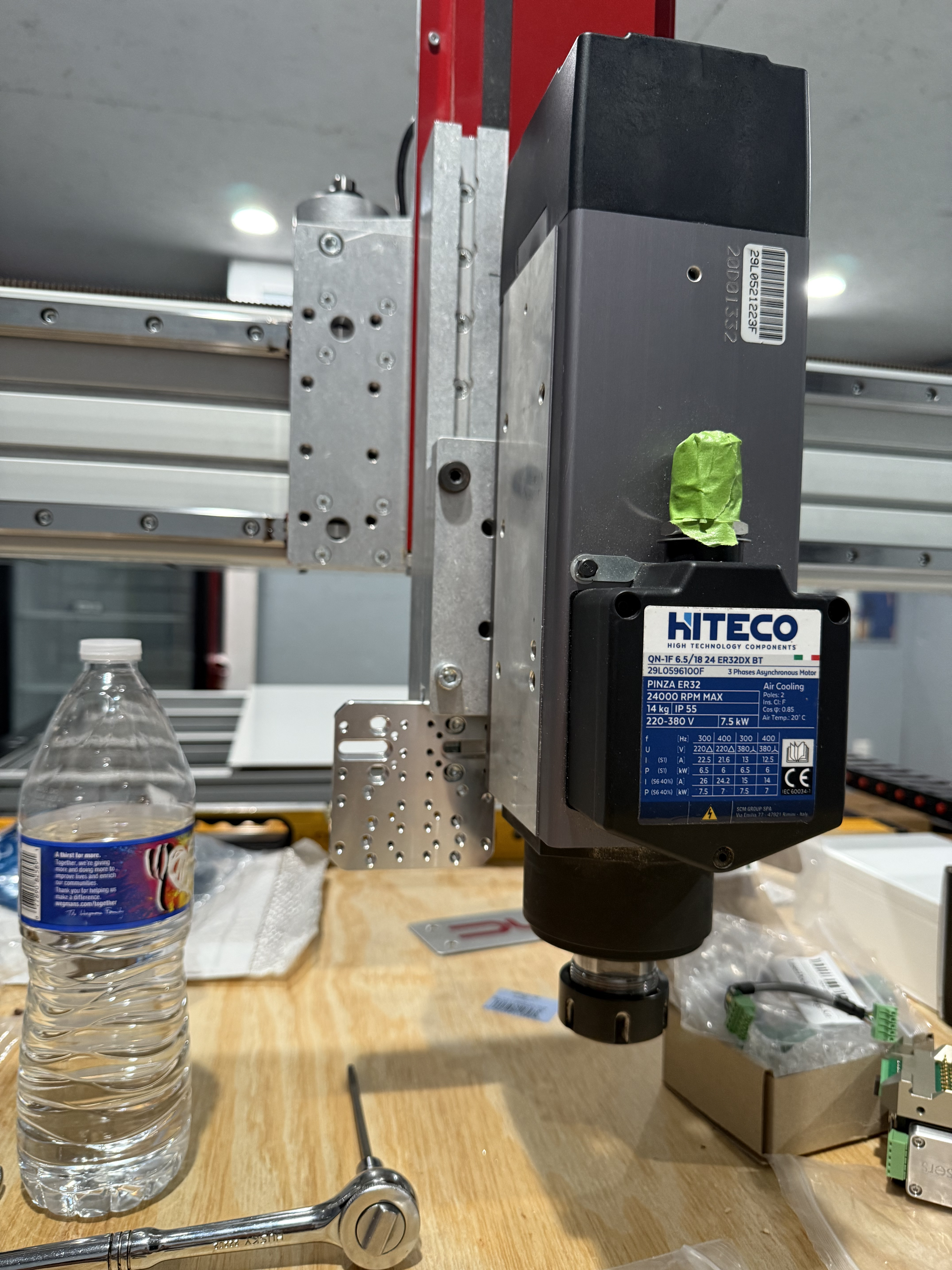
You can use any available output on the ESS for the PWM, and any of the port’s grounds should work. Most people (including me) use a Port 3 pin just because they are generally not used much, and that port doesn’t have any of AVID’s ribbon cables plugging into it (unless you have their laser kit or plasma kit).
Then you need to define the gate signal too (but you don’t actually hook a wire to it). That can be any available output (again, most use port 3).
When you say “armed”, do you mean the red button on the Opt adapter box, or the armed button on a Mach4 screen?
I have a set of screens on that same google drive. If you take the latest one, besides all the spindle support, there is a test fire button for the laser (low power so it doesn’t burn anything).
If you have it test firing from Mach4, you should be ready to run a Gcode file. You’ll need vectric or F360 post processors to generate the right gcode.
You can email me at jnwdwks@gmail.com if you have more questions or want to walk through what’s left.