The settings really depend on which rotary you get (There are a lot of them)
What I did was this:
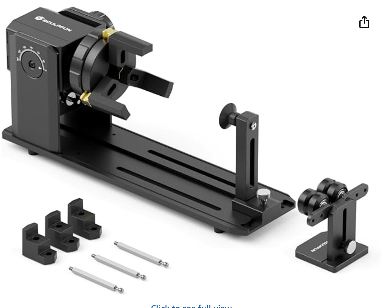
I ordered the rotary and then immediately too it apart to see what amperage the motor was. The two specs that I needed were stamped on the motor: 1.7 amps and 1.8 degrees per step.
Those are both pretty standard figures.
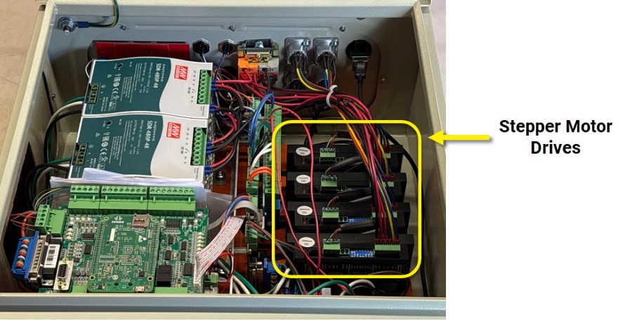
Our stepper motors run at much higher amperage, but our stepper drives have adjustable amperage:
If you look on the side of a stepper driver there are dip switches that you can configure. One set of them is for the amperage. Stock I believe we max them out at 7 amps, with the flipping of a few switches I was able to drop it to the lower amperage I needed so I didn’t cook the stepper motor in the rotary.
Our stepper motors are 4 wire (two wires per coil) and so was the stepper on this rotary. To find which wires go to which coils you can use a multi meter, or just pinch two wires together and see if the stepper gets a lot more resistance when you spin it. I did this method and I was easily able to find out which wires went to which coils on the new rotary.
Then it just a simple matter of running those four wires into the stepper driver plugs in the control box.
You’ll see on the side of the stepper there’s A+ A- and B+ B-. Depending on which pair you put into which, this can make the motor spin clockwise or counterclockwise.
You can decide if you want to hardwire it “correctly” or just do whatever and fix it in software.
Now the motor tuning part…
There are a couple of ways you can go about this… You can do the math ahead of time, or you can guess and dial it in…
There’s a great article here:
Without repeating that entire article, basically there are two things you need to get right in the wizard:
Steps per rev, and distance traveled per degree (Turns ratio)
Steps per rev is fixed… 2000 steps will spin the STEPPER motor 360 degrees. The second thing you need to figure out is how many degrees the motor spins given a particular command..
This can change depending on the geartrain that you have on your rotary. The Avid rotary is 10:1 reduction. This little guy I got is 4:1. I’ve seen a lot of 6:1 ones out there.
That article I linked should help you math it out.
Another method you can do is to navigate to CNCM/system/axis calibration (you load a G code job in there called "Axis calibration)
This will guide you through calibrating your axes. You can do a rotary this way. I ran the utility, made a mark on the rotary and then spun it 360 by hand jogging. I lined it back up with my mark and this utility told me the turns ratio and set it for me.
This is an effective way to do it, BUT if you’re off EVEN A LITTLE your errors can compound. I used this to get me “close enough” which helped me verify my math. I ultimately used the math formula for my final settings.