Mentioned in a project post last week, I am building a few pieces to supplement functionality of a rotary weld positioner in use out in the garage.
In this second installment the plasma table side of the CNCRouterParts / AVIDcnc was used to knock out a quick adjustable, rotary, material end support. Space out in the back corner of the garage where most grinding and welding operations are carried out is, in a word, limited. As such I wanted to combine this stand with an existing outfeed roller stand already in place in the workshop for use with the bandsaw and radial arm saw.
Like many other of the “fabrication” projects, this one proceeded with only minimal CAD work, just enough to make a few flat patterns, generate some G-Code and head out to the garage to the plasma table side of the AVIDcnc.
The parts are cut from an off-cut/drop of 1/4in mild steel flat bar. The cuts are knocked out with standard consumables, 45A, 130V for the THC, 0.6sec pierce dwell and 49Ipm travel speed. The small piece of 3/4in steel on the right is just to add a little extra mass to ensure the 85psi air blast does not move the piece while cutting.

And away we go, blasting through steel like butter…


This time around, I forgot to snap a picture of the parts coming right off of the plasma table. Instead, they went directly to the next processing step. There were 4 holes that possed locations where I wanted a slightly tighter tolerance hole. For those 4-locations, 1-per part, the CNC dropped in a plasma pierce to provide a center for a future processing step. One of those future steps is shown below. That pierce hole is used to locate the spring-loaded centering pin on the mag drill and align the annular cutter to put in a reasonably precise hole. A 1/2in annular cutter is just large enough to cut around the HAZ and any glass-hard spots that might have been left behind by the plasma cutter and affect a normal drill bit.


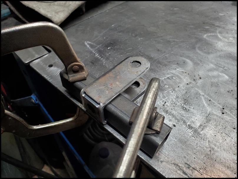
Below, are the 1/4in thick mild steel parts from the AVIDcnc plasma cutter after the 4x 1/2in diameter holes (1-per part) were put in with the mag drill and each of them spent a small amount of time (about 1min ea) getting to know the slack belt on the 2x72 belt grinder.
Knocking out parts like this so incredibly fast and easy, it leaves me wishing I’d bought this machine years earlier than I did.

While I was at it, some 1in x 1in x 1/8in-wall 304 stainless steel tubing was surrendered to the chop saw and the mag drill was used to pop some matching 1/2in diameter holes with the same annular cutter used on the plasma cut parts.


And next up it was back to the plasma table side of the AVIDcnc, this time with a sheet of 10Ga (0.135in) 1018 mild steel. This sheet has some gooe useable places to cut parts from yet left in it.


This next image shows, the part turned out slick and easy. The part has a couple cross cuts where it will be bent and welded up in a follow-on step.

And then the cut piece was folded over a scrap of square steel tubing. It doesn’t show in the photo, but there is a small rectangular scrap of 16Ga(~0.0625in) mild steel under the tube this piece is folded over to leave a little extra room. In a later step those plasma cuts that alow this be be bent up with minimal effort will be welded closed.
The next image shows most of the pieces laid out on the welding bench. Note this photo is out of order as the part on the right hadn’t been folded yet.

And yes, you guessed it, next up some welding. Welding stainless to mild steel is somewhat interesting. Here 0.030in ER309L wire was used as it is recommended for joining stainless-steel to mild steel. I’ve only done a small amount of stainless-steel to mild steel welding and it is always interesting. In stainless steel the weld heat moves/propagates through the material at a much slower rate than in mild steel, so the weld puddle will stay hotter on the stainless-steel side and significantly allow the weld puddle to be pulled away from that side as it cools and the mild steel side spreads out the heat and cools first.
I didn’t capture any photos of that, so this first image, below is 2x-pieces of 304 thick wall stainless-steel tubing being welded up with an extra heavy bead.

And back to a little more welding, welding on a 1/4-20 “nut”. I made a large handful of these easy weld 1/4-20 nuts a few projects back and they have been coming in pretty handy. I used three of them in this project alone.

There was quite a bit more welding, but this gives a decent flavor for it. Next up the assembly was bolted together to take a first look and give it a fit-check.

I did not have the correct diameter washers to go with those bearings, so for this mock-up I threw in some galvanized steel washers that I had on-hand and did not fully tighten up the 1/2-13 hardware. I’ll go back and knock out a set of properly sized stainless-steel washers on the plasma cutter later on.

I also went back and fabricated some quick tee-handles with some 1/2dia stainless-steel bar stock and a pair of 1/2-13 coupling nuts.


And then it was time for some powder coating…

The stainless-steel parts were masked going into the powder coating process as only the mild steel parts need protection for use out in the garage.


This came together just as I had pictured it when initially planning it out. The photo below shows why that angular joint is needed in the middle of the upright. depending on whether the legs of the out feed roller stand are spread more or less, the angle of the upright changes. The adjustable joint, 1/2-way up allows the user to bring the rotary bearings back in axial alignment with the stock being supported.

In the photo above, if one looks closely, they can also see that I hammered in a pair of plastic end-caps on the stainless-steel tubing, just to keep one from snagging shirts/elbows.
Not the best photo and it is pretty crowded back in that corner of the garage as I’m re-arranging things out there, but this last photo gives one and idea of how this project turned out. Here it is supporting some 3in-dia x 3/4in wall aluminum extrusion.

I hope someone out there finds this useful or derives inspiration for a project of their own based on these ramblings. ![]()
-Kenneth


