I’ve had an old Grizzly Industrial 20-ton hand cranked bottle-jack style press in my shop for ~18 odd years now. Ever since the day I bought it there have been a handful of small upgrades that would make it easier to use. (I do use it a surprising amount.)
With the addition of the AVIDcnc router & plasma system to my tool set in late 2018 and the plasma learning curve and large number of “first” projects out of the way, I pivoted and took on this, long-time coming, shop upgrade.
The basic upgrade plan looks like the following. Yes, you guessed, it high-level layout in MsPaint instead of CAD. Okay, it isn’t quite a napkin sketch, but you get the idea.

On the press I use a good number of production style broaches for cutting keyways. Instead of using a separate collar and spacers and shorter key, these are single pass broaches, full round on the back and are quie a bit longer to facilitate the single pass nature. Since these are single pass broaches, the ones I use on a regular basis range from 11" up to to 24" for cutting keyways.

The bottle jack in my press has a bit over ~5" stroke. That means I often have to stop and reposition the table / work piece multiple times. given that the current design of the table one lowers the left side pin & table (leaving that side down by 6", then the right side (or vise versa) in two separate operations, the work is invariable left at an extreme angle while repositioning the table.
The advantage of the cable system routing that I have selected for this project is that while the table is lowered, it remains horizontal. One slightly lifts it, drops down both rest pins (more on these further below) and then lowers the table horizontally down onto the new seat. I most certainly did not come up with this idea. Older larger / heavier Dake industries machines shipped with a mechanism like this and so did a handful of other manufacturers. Why Grizzly Industrial didn’t offer this as an add-on is beyond me.
One of the hardest parts was moving the press frame from the indoor robotics studio out into the garage over a rough lawn and then back. Thanks to my neighbor Otto for coming to the rescue and helping out on that one. One man and a dolly would have been just a bit to sketchy, as the thing just wanted to tip sideways, even when strapped on, but having a 2’nd man there to stabilize the load made it go a lot easier. (Thanks Otto!)
I hoisted up the mag-drill and immediately went to work poking all sorts of holes to mount simple pullies designed for 1/4-in wire-rope to the frame.


If you look at the scrapes in the paint, above, you can see some of the handling as this hydraulic press has been subjected to as it has been moved across the US and back and around the greater Pugetropolain flood plain a few times. Yup, riggers move the lathe and mill, etc. But the press usually waits behind for the movers so it tends to get slammed around quited a bit.
And then it came time to fabricate the first bracket. This one was so simple that I just went ahead and fabricated it by hand from a small off-cut of angle iron. I then punched 5-holes and zipped out the slot on the band saw, then touched it up / softened all the edges and rounded the corners on the 2x72" belt grinder.

I weighed making it removable vs how fast it would be just to attach it permenantly and decided to just zip it into place with four stitches from the MIG welder. Since this is 1/4in angle and 1/8in angle it was easy to just dial things UP and go in hot. You can see that I did take a minute to grind back a bit of paint rather than weld through it.

And then promptly, I did a rattle can dance to keep it from rusting up. There always seems to be 1-can of red & white,and at least 4-cans of grey and black in the paint cabinet here. No it does not match the red on the rest of the machine and I am quite okay with that! ![]()


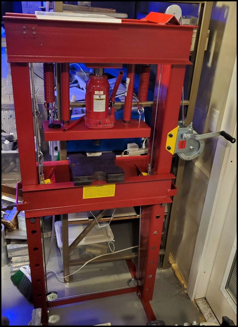
(the following picture is out of order, taken after the press had been moved back into the studio and had been in use for a bit.)
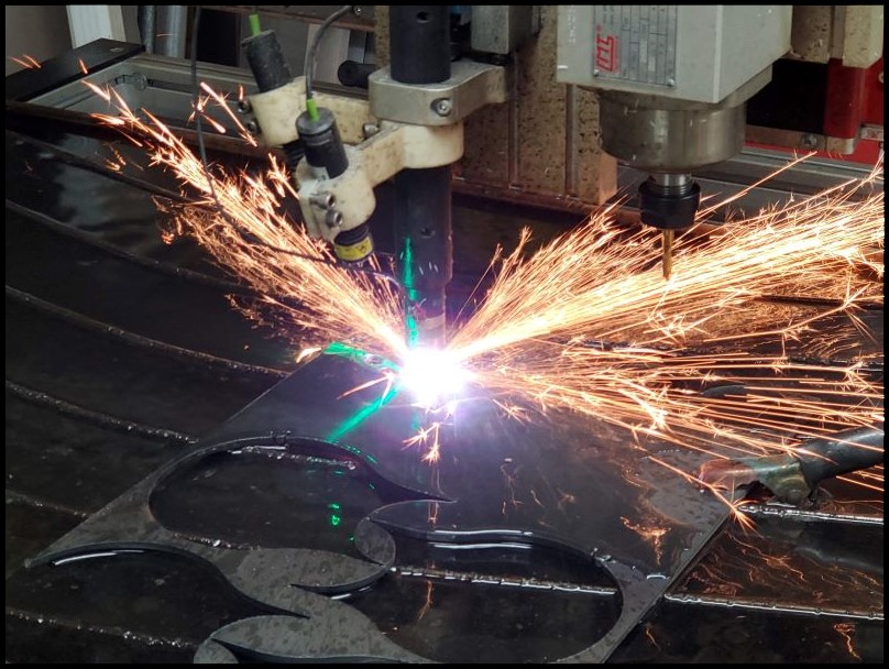
But then it was time to make some more brackets. Could these have been free-handed? Yes, the need for precision is reasonably low on these, and some carful layout and time with the ange grinder and drill press or Mill could have done the trick, but when on has a CAD system they’ve been using since '95 and a plasma table to “play” with, it’s a no-brainer. This type of fabrication work just goes sooo very fast with a plasma table.

The material here is cheap 10Ga A36 mild steel.


And Viola! Soo fast. You can see from the cut below that I ws running on some pretty old consumables and I hadn’t dialed in the right pause timing after initiating or turning off the arc yet, but even still the parts came out great. It wasn’t long after this project that I wrote a post-post processor to take G-Code files from my old CAD system and insert all the necessary bits to automate the process of making them plasma aware. But at this point, I hadn’t taken the time to do that yet.

The parts were run through the belt grinder to soften edges and then the little “coaxing” hammer was used to “gently” “ease” the steel over into the shape of the brackets I needed. ![]()


A quick pair of test fits… I had planned to buzz down the outside of each of these with a weld bead, but with the parts in hand, just the way they were, I made the executive decision to skip that. Time will tell if it was the right decision, but my best guess is that they will perform adequately. With the parts in place I used a sharpie to transfer the last of the holes to the frame and table. Luckily the larger holes in the frame were 1/2" so I could use anular cutters in the mag-drill which is a surprisingly smooth operation and the remainders (only 5/16") were done with a hand drill and a stepped drill bit.

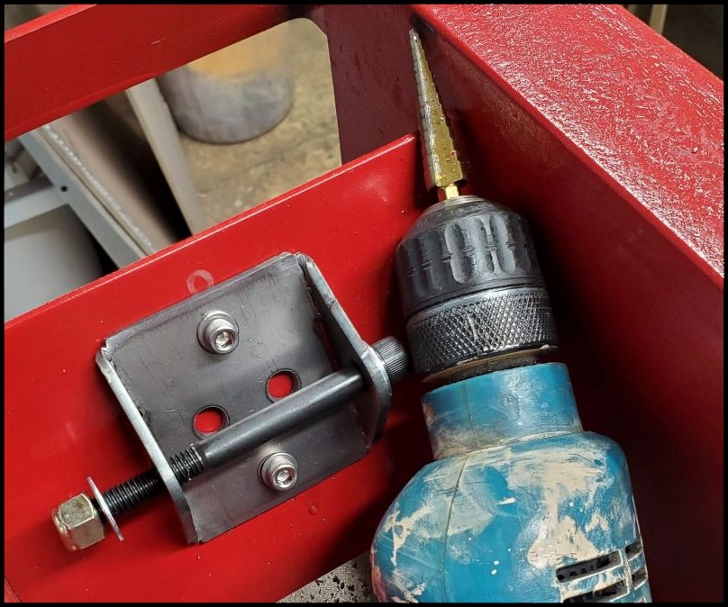
You can see in the photo below, that I am using nyloc-nuts and that the screws are over-length. I happened to have these screws on hand so I ran with them.

After the test fit demonstrated that everything was going to line up just-so, it was on to powdercoating. One part came out a little bit light as that one did not receive a second “hot-flock” and I considered going back for that, but hey, after the parts are mounted, if you don’t tell, only the two of us will know, and they are still going to last easily 50-yrs.

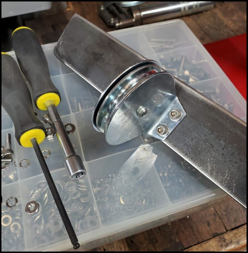
For the purposes of permanent installation, the bend radius of the wire-rope/cable needed to be taken into account. Even with an eye installed into the cable, that small diameter of the bolt wasn’t going to be the greatest so I popped over to the lathe and knocked out some aluminum radial spacers.


Below is a test-fit / mock-up with a loop I had made for a different project, but it was the same diameter cable so I tested it here. There is a cable eye installed in the wire rope loop on hte left, and there is not one installed on the right.

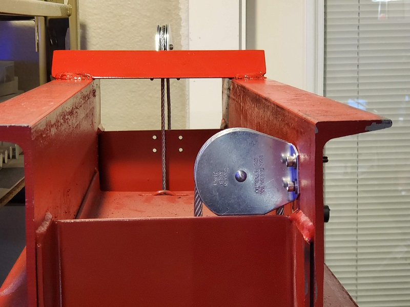
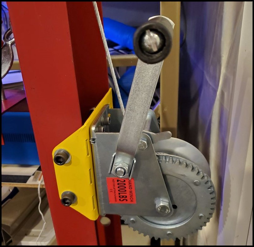
This is how the real cable termination looks in-place on the machine. I haven’t put the 2’nd crimp into the locking crimp in case in need to make adjustments yet. Part of me said to go back and re-cut the spacers from larger diameter material and cut in a centering hemispherical relief in the middle to keep the wire-rope centered / seated. At the same time the other 1/2 of my brain screamed, good enough… ![]() From the photo, below, you can see which side won.
From the photo, below, you can see which side won.

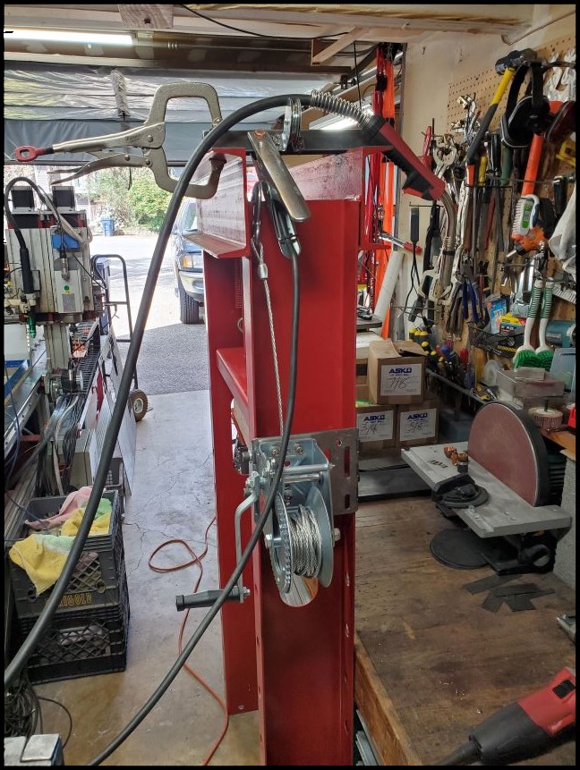
The hand crank with locking reversible pawl ratcheting mechanism (cheap from eBay) was installed. These are commonly used for pulling small boats onto trailers, etc and it works out perfetly in this case. With the 1" thick AR-500 press plates installed (overkill for a 20-ton press) the assembly is lifting about ~160lbs.
And everything was ready to take for a spin.
While I was at it on this press there was one other upgrade that was desperately needed. The adjustable 1" diameter pins that the table sits on arrived rusted. I don’t know what kind of steel they are, but they always seem “unfinished” and want to push through the holes when I’m trying to put them in place. They need a simple “stop” feature.

Soooo back to the AVIDcnc plasma table. I’ve got a plate of 3/16in thick material left over from previous projects and there will still some useable spots from which I could knock out a couple small parts.


The press pins were then cleaned up on the belt grinder and prepped for welding.


After that a small bit of round tube was lopped off on the bandsaw and welded in place as a simple handle. I’m definitely on the home garage / weekend warrior side of things when it comes to welderizing, but this will do for a handle. That is reasonably thin-wall tubing that I’m attempting to attach to 1" thick bar stock so in a step (not shown) I had to pre-heat the solid bar with a map-gas torch for a few mins.

They came out great!

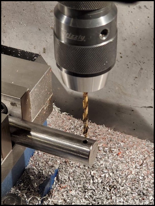
While I was at it these parts went into the studio, and on the mill they were cross drilled and threaded for a spring loaded ball detent set screw, to help one feel / when they are seated.
And finally, the parts are powder-coated…

Plastic end-caps were added, hammered into the steel tubing, …

And then installed…

After all these years, the two above changes and the addition of a simple mag-mount flexible work light make this machine much, … much easier to use especially when it comes to the 18" and 24" broaches or just setting up for different jobs.
Wish I had owned the plasma cutter years ago to make knocking out weekend projects like these, so much easier. The mill just isn’t as well suited to knocking out quick projects in larger flat stock. I find that between projects for myself and several of my neighbors (whether it is car restoration, go-kart parts, custom brackets, signs, furniture projects, boating parts, workshop improvements, etc.) I use this plasma cutter most weekends! From 35yrs of precision and machining robot parts on a mill to the freedom of fast cut and run in plasma-cutting and welded-fabrication, with little-to no setup, I feel late to the party. ![]()