I have been using Corbins’s stuff for quite a while and even went from using forks to 3d printed cups so there is no slide necessary. It is working very well and I gained back my full bed length
I hadn’t considered cups. I have a mixture of ER20 and ER32 tool holders so I’d have to be judicious about making cups work.
I think Chad got his up cup design from Pwn CNC: Tool Rack – PwnCNC
I started on a design but never finished it. It’d be cool to have an indexable square bottom that attaches with strong magnets and/or some quick release bolts. Then you could easily remove them to get extra cutting area.
Now that I think bout it… a sliding fork design would probably work with that idea too! Some people are using my 3d printed holders with good success. I didn’t use them as I thought they were too weak.
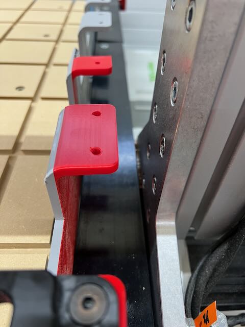
I just looked at the tool cups, and then it occurred to me that a lot of the room I’m stealing from my work surface is due to the minimum bend radius for send cut send. So… for grins and since my tool fork rack is a mirrored design, I reversed it and attached the forks to it and reclaimed 2”+ of work surface!
I don’t think I’ve ever used materials over 54” in width so 4” of loss is not going to be a problem at all. Thanks for making the brain juices flow!
Were you able to find a way to get the drawbar to release to auto change a tool through m15/16 coManx with the av spindal?

Nice! What material did you use for the holders? Did you design the forks or find that STL somewhere? Any strength issues?
Look at all those tool forks! I only get 7 tools ![]()
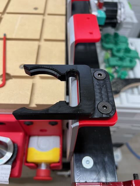
I used pteg used your base design but modified and used a fork design off of thingyverse but modified. Seems pretty strong have pushed it a few times jogging to fast and no breaks. I can share if anyone is interested.
Yeah, send me the fork design (CAD/STL/whatever) - I’d be interested to check it out! corbin at corbinstreehouse.com
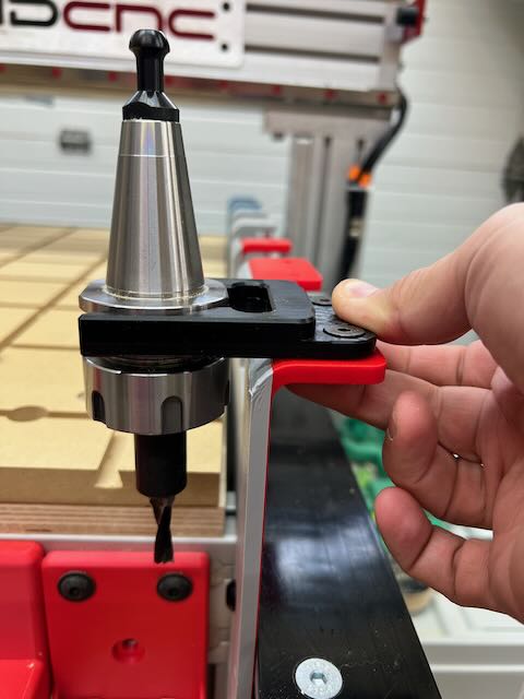
Here you go, let me know what you think. I have not had a chance to run them in a successful tool change. Hoping to hear back from avid on how to get the drawbar to unclamp on the av70s. Thanks for all your downloads, used your dustboot, the atc download (have all locations set) and your base started this design.
Austin
(Attachment ISO30ToolHolderClipBase and fork this one is correct.3mf is missing)
What is your email? I tried sending through the email from forum but attachment was denied.
I got it, thanks!
RE spindle, here’s what I think you do (from another thread):
Schematic: Spindle Controller Schematics - Plug and Play Spindle / VFD System Manual
It looks like Pin 1 of the M12 8P connector can just be used to wire up the drawbar command, which can be put into “plasma torch” like I talk about in my setup diagram.
I read through the AV40S setup; it looks like the M12 8-pin cable is connected directly to a 24volt power supply. You could connect that to a female connector (somewhere, maybe another box temporarily) that provides 24volts for the power and controls the drawbar signal on p1.
Or, you could run a shielded cable from the M12 box on the spindle itself, and tap directly into drawbar signal and wire that into your Ex control box for the “plasma torch” relay #6 output, and start playing around with ATC capabilities right away.
I tapped in to the 24vdc in the spindal box for power to the drawbar pins 2&7. And I connected pin 1 to relay 6no I tried connecting the com on relay 6 to 5v on interconnect board and does nothing along with ground and a neg24 on interconnect board. Nothing. Any suggestions?
Eric probably knows the exact details; I am only guessing as I can’t look into the spindle to see how it is wired.
It says “N.O., Sourcing. Close to release the tool.” I’m guessing you would use the relay to pull it to ground to make it release the tool. So, pin 1 would go to one side of the relay (normally open side), and the other side (com) of the relay would go to the 24v ground. When the relay activates it will close, pulling pin 1 to 24 v ground.
Just a guess though, I take no blame if it fries something!
Yes this is what support sent me aswell. relay is turning on but nothing is happening. checked the microcontroller on the spindle for a loose wire but everything was good. thanks for the response.
I’d check the 24v+ and 24- with a volt meter at the spindle to make sure it has power. Then I’d try (without a tool in it) taking a wire from pin 1 and putting it to ground and seeing if it opens the spindle. If that works, then the problem is somewhere else.
I have 24v power at the micro controller and the push button is working as it should at the spindal. Tried touching to ground and nothing. I did try hooking pin 3 up to the relay and the drawbar releases but then close right away not something I would trust for a tool change
The 8 pin schematics are all here: Spindle Controller Schematics - Plug and Play Spindle / VFD System Manual
If you’re having trouble actuating the drawbar make sure you’re using the same power supply that powers the spindle and not the one in the control box unless you tie the grounds together.
I connected to The bus bar to the left of the mdr40-24 in the vfd controller box.