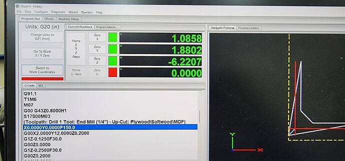
Instant fail: Error X Axis commanded over softmin?

Hello! I’m not a total noob, but I’m new Mach4 for sure.

Just got my new PRO4896 up and running. I ran the Vectric squaring and tramming file and the machine is dead on square. Pretty sweet. Coming from an X-Carve…this machine is quite the improvement and I’m super excited to party.

I have a 36"x 36" sheet of 3/4" MDF secured to the machine as a temporary wasteboard and I drew up a simple program to drill some 1/4" holes for some alignment dowel pins. My material setup in Vectric looks good. I homed the machine and then used the touch plate to set my material X,Y,Z…However, when I run the G-Code it fails on line 23 with “Error X Axis commanded over Soft Min”

Is it actually failing on line 24 and Mach just shows the last line ran? I’m guessing it’s failing on line 24. Either way…I have no idea why it’s failing with that error.

23 X0.0000Y0.0000F150.0
24 G00X2.0000Y12.0000Z0.2000

I looked and I don’t have a “Soft Min” set for X which further confuses me. I’d get this error if I DID have a soft minimum set.

( WasteBoardHoles )
( File created: Sunday November 06 2022 - 03:52 PM)
( for Avid CNC Machines, post processor v3.0 )
( Material Size: X= 36.000, Y= 36.000, Z= 0.750)
( Z Origin for Material = Material Surface)
( XY Origin for Material = Bottom Left Corner)
( Min Program Extents: X= 0.000, Y= 0.000, Z= -0.750)
( Max Program Extents: X= 36.000, Y= 36.000, Z= 0.000)
( Home Position: X =X0.0000 Y =Y0.0000 Z =Z0.8000)
( Safe Z = Z0.2000)
()
(Toolpaths used in this file:)
(Drill 1)
(Tools used in this file: )
(1 = End Mill {1/4"} - Up-Cut: Plywood\Softwood\MDF)
G00 G94 G20 G17 G90 G40 G49 G80
G91.1
T1M6
M07
G00 G43Z0.8000H1
S17000M03
(Toolpath: Drill 1 Tool: End Mill {1/4"} - Up-Cut: Plywood\Softwood\MDF)
X0.0000Y0.0000F150.0
G00X2.0000Y12.0000Z0.2000
G1Z-0.1250F30.0
G00Z0.0000
G1Z-0.2500F30.0
G00Z0.2000
G00Y6.0000
G1Z-0.1250F30.0
G00Z0.0000

When you say you don’t have a soft min set for X, where are you looking?
The table is in the Mach4 control setup and should look something like this (except your Y will be more like 97).

Yep. That is where I was looking. This is what mine looks like.

1 Like

Mach4 has a look-ahead feature of something like 20 lines of code by default. I’m guessing you have a high X movement commanded on or around line 44.

Ah! Excellent insight! I will look closer at that. Thank you!

1 Like

Hmmmmm I still don’t see anything weird or out of bounds…

( WasteBoardHoles )
( File created: Sunday November 06 2022 - 03:52 PM)
( for Avid CNC Machines, post processor v3.0 )
( Material Size: X= 36.000, Y= 36.000, Z= 0.750)
( Z Origin for Material = Material Surface)
( XY Origin for Material = Bottom Left Corner)
( Min Program Extents: X= 0.000, Y= 0.000, Z= -0.750)
( Max Program Extents: X= 36.000, Y= 36.000, Z= 0.000)
( Home Position: X =X0.0000 Y =Y0.0000 Z =Z0.8000)
( Safe Z = Z0.2000)
()
(Toolpaths used in this file:)
(Drill 1)
(Tools used in this file: )
(1 = End Mill {1/4"} - Up-Cut: Plywood\Softwood\MDF)
G00 G94 G20 G17 G90 G40 G49 G80
G91.1
T1M6
M07
G00 G43Z0.8000H1
S17000M03
(Toolpath: Drill 1 Tool: End Mill {1/4"} - Up-Cut: Plywood\Softwood\MDF)
X0.0000Y0.0000F150.0
G00X2.0000Y12.0000Z0.2000
G1Z-0.1250F30.0
G00Z0.0000
G1Z-0.2500F30.0
G00Z0.2000
G00Y6.0000
G1Z-0.1250F30.0
G00Z0.0000
G1Z-0.2500F30.0
G00Z0.2000
G00Y4.0000
G1Z-0.1250F30.0
G00Z0.0000
G1Z-0.2500F30.0
G00Z0.2000
G00X4.0000Y2.0000
G1Z-0.1250F30.0
G00Z0.0000
G1Z-0.2500F30.0
G00Z0.2000
G00X6.0000
G1Z-0.1250F30.0
G00Z0.0000
G1Z-0.2500F30.0
G00Z0.2000
G00X12.0000
G1Z-0.1250F30.0
G00Z0.0000
G1Z-0.2500F30.0
G00Z0.2000
G00Z0.8000
G00X0.0000Y0.0000
M05
M09
M30
%

Just curious, when you get the error, can you toggle back to machine coordinates and see where the x-axis is showing? It may have something to do with your machine home position. Let us know what you see.

Good idea. I will try that tonight and report back.

Ok, that looks right. You do have a soft min for X, it is 0, in machine coordinates. So you would be looking for a location in Gcode where it is commanded past 0. It could be 20 or more lines ahead due to the lookahead buffer. It will be in work coordinates in the Gcode though, so you have to convert.

Ahhh interesting. That makes sense. Hopefully we are onto something here.

1 Like

I read ‘over’ and jumped to thinking in ‘maximum’ but you clearly stated ‘Soft Min’ that’s my bad!

Ok here we go…I tried again just a few minutes ago. Same error…

I hommed the machine like normal and then I used the touch plate to set my work coordinates.

Work Coordinates:

Machine Coordinates:

Looking through the GCode I can’t see anything below the “0” soft limit? Wouldn’t that be a negative number in the code if it was?

There isn’t anything funkey from what I can tell…but I also just popped out of a fried rice carb coma…I’m totally stumped.

maybe check your x home sensor and block,make sure its tight,
the x home sensor and the x softmin are related

Ya, it should tecnically be negative in both work and machine coordinates. However, the difference between your X machine and work coordinates is only about 15 thousandths, and you do have it going to X=0 in the Gcode, so it is getting very close.

What happens if you set your work X and Y zero just a quarter inch in from the machine X and Y zero, does the toolpath run ok then? You can just set Z0 an inch or two high so it doesn’t cut anything).

1 Like

Man, that worked…and at first it made ZERO sense why…I couldn’t understand how I could get a negative number, but now I see that what I’m looking at for the WC includes the touch plate offset…SOOOO the actual 0,0 location it’s calculating is LESS than the MC 0,0 resulting in the negative number. The math wasn’t adding up for me, but I wasn’t considering the offset…Sheesh.

Most people have their working area X and Y zero a bit inward of the Machine X and Y zero, but I suspect if you run the work right at the edge all the time you’ll probably have this problem sometimes.

I usually have my stops set more in the middle so I have room for clamps and junk around what I’m working on, and I only get close to the soft limit boundaries when I’m working on something really big.

Yep, exactly. At first I was a bit worried, but now that I understand this situation, it shouldn’t be a problem moving forward. I was zeroing on the spoil board to peck some holes it for work alignment. Either way I lost less than 0.25" so I’m golden.

Thank you all for your help. Normally I don’t really care for public forums, but so far this one is shaping up to be different. Really excited about the community we are building here.

This one is good, and the Facebook AVID group is very good as well. I’ve learned a lot there as well.

1 Like

I am having the same problem … “Error X Axis commanded over Soft Min”

I am trying to flatten my spoilboard.

I’m not sure what it means when you say " if you set your work X and Y zero just a quarter inch in from the machine X and Y zero" What specifically are we doing here. (I’m brand new at CNC)

Thank you!

Since you said you are new, I’ll give a little extra background. You have two basic types of coordinates. Your machine coordinates are the actual physical limits of its range. So X0, and Y0 are as low as you can go, and then the other end of the table will be the other end of the range, and it will depend on the size of your machine. Z also has a 0, which is the top of travel on an AVID machine.

When you run the homing process, what is happening is that the machine is traveling (slowly and carefully) in the direction of Z, then X and Y until the sensors find the end of travel. This is where the machine will set the Z, X, and Y coodinates of zero. You need to do this every time you power on your machine, or your steppers lose steps (like if you crash or hit the Estop button while its moving).

The second sent of coordinats is the work coordinates. These are a somewhat arbitrary location within the machine coordinate range where you want to operate for a given run. Sometimes this is a fixed location on your table because you have a vice, or some other jig to hold your work all the time, or if you are like my and you attach your object to cut in different places depending on its size or what you are doing, it will change from job to job. The work coordinates have a Z, X, and Y zero location as well, and these are the numbers that you need to pay attention too with respect to your design, because whatever your reference point is when you design an object (middle, or one of the corners for X and Y, or top or bottom for Z typically), that is where you want to set your work coordinates in Mach4 with respect to that same location on the physical workpiece. You can set your work coordinates manually by positioning an axis via jogging, and then hitting the “Zero” button for that axis in Mach4. You can also use a touchplate or probing device and routine to do it as well. Basically, you are telling Mach4 where inside the machine coordinates you have placed the part you are about to cut.

You can machine anywhere relative to your work coordinates, because that is just a reference point to keep the job you setup on the machine on the same page as the design you did in CAD/CAM. However, you can NEVER exceed the machine coordinates if you have soft limits turned on in Mach4. It will give you the “Error, “axis number” axis commanded over the limit” error and stop because it can’t physically go off the table like Bean was getting.

Since he said he was trying to machine off his spoilboard (which is usually built to be about the same size in X and Y as the top of the machine, and therefore the maximum range of travel), I suspected that he was setting his work coordinates so close to his machine coordinates that the tool path maybe was telling the machine to run outside the allowed range (machine coordinate range), so I just asked him to move the work coordinates in (in other words, jog into the interior of the table a little further before setting X and Y zero) to see if that helped.

The best way to check out the placement of the workpiece and its associated work coordinate settings is to set work coordinates and load the Gcode, and then see if your toolpath is within the dashed yellow machine coordinate envelop. Below I loaded a toolpath and didn’t set the coordinates properly and you can see the toolpath (a circle) is outside the dashed yellow line. If I were to try and run this I would get the same error.

Hope that wasn’t too longwinded to make sense.

1 Like