Maybe this project doesn’t have the biggest “cool” factor but it involved some machining I seldom do. Further it provides an opportunity to showcase some of the machines I have built. A request came to my son (a CNC machinist) to make a metal version of the tool shown in the photo, which he passed on to me; it’s made of plastic and the owner is sure it will get broken. Likely.

My son recommended the tool not have a long arm on it, so a screw driver type tool was designed. I didn’t take any pics of the lathe work, but it’s just a cup-shaped cylinder with a stub to attach a handle. In the photo below the teeth are being cut with my shop-built micro controlled rotary table on my shop-built horizontal mill. The mill is a revised Phoenix Mill shown in an early issue of Home Shop Machinist. More on the machines later.

The tool with the teeth complete
The walls of the cup are quite thin so I was very cautious cutting the teeth; a shallow cut for all the teeth then increasing the cut depth and cutting all the teeth and so on. After some trimming and attaching a handle with epoxy the finished tool is shown below along with plastic tool.

I went real “plain Jane” with the handle. The hole to release excess epoxy can be seen. It should work fine.
The photo below shows DC Servo driven rotary table.

The servo motor is repurposed (from a printer likely). It had a velocity encoder originally but I needed a position encoder for the intelligent motion controller (LM628). The salvaged encoder is a “through hole” version that required a mount. A 3D printed tether mount was built and can be seen between the motor and encoder.
The front panel of the box containing the micro and intelligent motion controller is shown in the photo below.

The control box provides a significant menu structure to allow most of the features you might want in such a tool as can be seen in the main menu. There is a complete article about this tool in Digital Machinist magazine.
The photo below shows my Phoenix horizontal mill; it differs considerably from the original design. The head assembly was cast by one of my buddies. We shared machining tasks on the head. The section with the link belts is my design. The original used multiple stages of step pulleys and jack shafts taking up too much bench space. There are no step pulleys here. The DC motor seen at the top was salvaged from a centrifuge and is speed controlled by a standard KBC DC Motor Speed Controller.

Below is the speed controller open showing the tachometer circuit added.
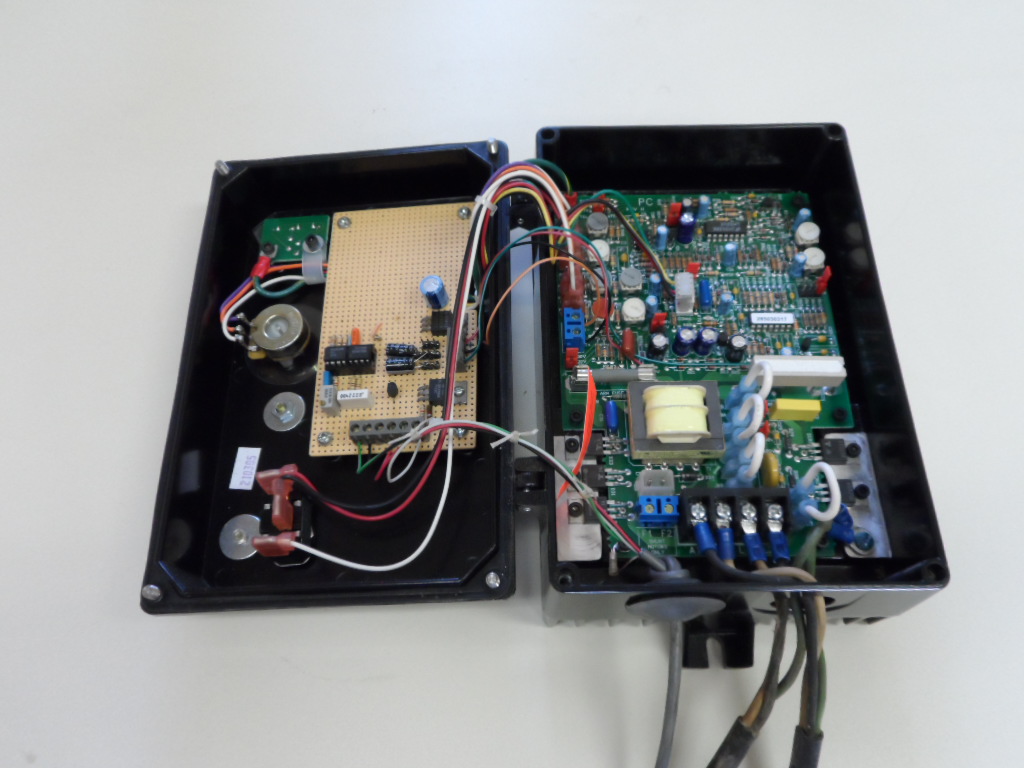
This motor may have had a tachometer originally; not sure what I did with it. But now it needed an electronic tach and the picture below shows the interrupter and disc.

The modifications to the Phoenix Mill are discussed in more detail in my article in Digital Machinist.
Maybe I should admit here that this is the first legitimate job this rotary table has done. Sometimes I build tools just because it’s a challenge and fun.